Introduction
“Which way’s up?”
With rocks, the answer is not always clear.
If layered rocks have experienced mountain building, they may be rotated from their original horizontal positions into vertical orientations, potentially confusing geologists, since the principle of superposition no longer applies.
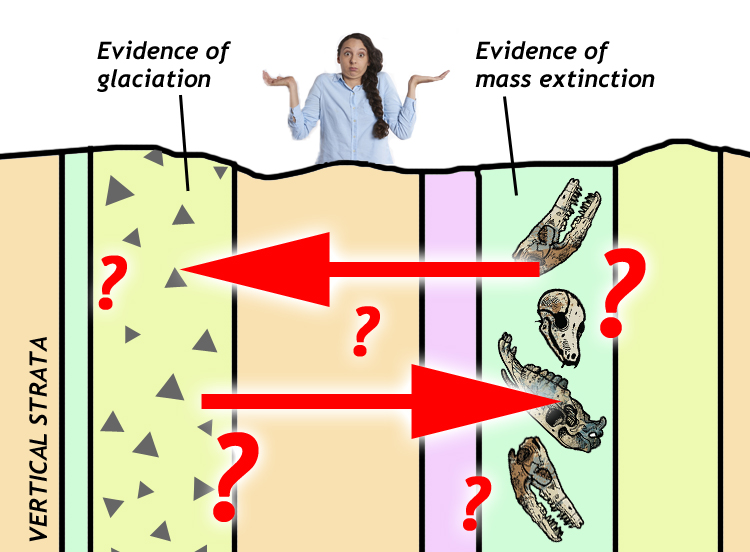
Consider the hypothetical example illustrated in the image at right: you discover a vertical sequence of strata. In one layer, you find evidence of a mass extinction event. In another layer, you find evidence of glaciation. Did an ice age cause the extinction? Or did the extinction somehow trigger the ice age? In order to pose intelligent questions about causality, you need to know which one is older. The older event can influence the more recent event, but not the other way around.
Even more extreme is when compressive stresses associated with convergent plate tectonic settings manage to fold beds into up-side-down positions. If the beds are up-side-down in such a tectonic inversion, it could really throw off the interpretations of the Historical Geologist: they would be reading Earth history backward!
In such situations, we need reliable tools in order to accurately interpret which direction was “up” when the rock originally formed. We call these patterns that look different right-side-up compared to up-side-down by the general term “way-up structures.” Some geologists also call them “geopetal structures.”
Way-up indicators are critical for figuring out the correct sequence of geologic units. The help us determine “younging direction,” the direction in which strata get younger. (This is the same as paleo-“up” or “facing direction.”)
The welter of terminology shouldn’t turn us off: it’s an indication that geologists put a strong emphasis on finding and relying on way-up structures. Consider this example:
Three layers are shown in outcrop at Earth’s surface, color-coded green, blue, and yellow. They are folded into what appears to be a series of anticlines and synclines. Given superposition alone, we would assume the lowest one is oldest, and the uppermost one is youngest. However, way-up structures in these three units point downward as the “up” or younging direction. Therefore, the exposed layers are part of a larger-scale fold, and the upper (upright) portion of that fold has been removed by the forces of erosion. Without the way-up indicators, we would have been fooled. So they are very important.
So what are these geopetal tools, exactly?
The key thing is that a way-up structure must be display some difference between its top and its bottom. They always look different up-side-down compared to right-side-up. In sedimentary rocks, the following way-up structures can aid the historical geologist in figuring out the paleo-“up” direction:
-
-
- cavity fills
- crossbeds
- ripple marks
- mudcracks
- graded beds
- loading structures
- sole structures
- burrows
- stromatolites
-
In igneous rocks, there are fewer options, but a few that are handy include:
-
-
- vesicle concentration
- apophyses
- pillow structures
- in a few rare intrusions, primary structures including grading and cross-bedding(!)
-
Metamorphic rocks develop no way-up structures as a consequence of metamorphism, but sometimes primary structures in a sedimentary or volcanic protolith can potentially survive as discernible patterns in lower-grade metamorphic rocks. Higher-grade metamorphic rocks are so thoroughly recrystallized that any original geopetal structures would be destroyed.
A note of caution
Be cautious about leaping to big, important conclusions from a single way-up structure. The way-up indicators shown on this page are hopefully straightforward, but nature is vast and varied. Examples seen in the field can frequently be ambiguous. The careful historical geologist will search for as many examples as possible; to see if they agree with one another. Careful geologists seek a preponderance of evidence before settling on an interpretation.
Sedimentary way-up structures
We’ll begin with an examination of way-up structures in sedimentary deposits, whether lithified into sedimentary rock or in an unconsolidated state (but after deposition).
Cavity fills
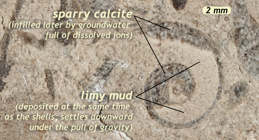
When an empty space exists in a sedimentary deposit, such as the protected little hollow under a shell, it can be partially filled by sediment. We call this little pocket of space a “void” or a “cavity.” If the cavity is entirely filled with sediment, it’s useless as a geopetal structure. It only has geopetal value if it is partially filled in with mud. In fact, this is geopetal in the strictest sense of the term: it refers to these cavity fillings. Here is how it works: the mud settles under the influence of gravity, lining the bottom of the space (but not the top of the space). Later, as groundwater moves through the sediment, it carries with it dissolved ions, which may bond together, filling the available space with crystals. In the example at right, the crystals formed are of the mineral calcite, which occurs in a coarse form geologists call “spar.”
Use this principle to examine the following image, showing a cross-section through a bed of limestone collected in West Virginia. We have intentionally placed it in a vertical position for you to examine. As you will see, the limestone includes many snail shells (gastropod fossils). A lot of them show this key pattern of infilling with two substrates: gray limy mud and white calcite spar. Note that because the shells are made of calcite also, both the original shell and the subsequent spar appear the same coarse crystalline white:
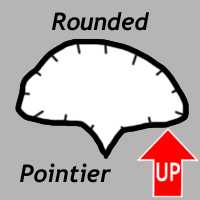
Which way is depositional “up” in this sample? You can use the rotation tool at lower right ![]() to test various orientations, until you get the mud at the (original) bottom and the spar above it in the (original) top of the available space.
to test various orientations, until you get the mud at the (original) bottom and the spar above it in the (original) top of the available space.
Hopefully you determined that the side of the sample next to the pencil was originally “down.”
The sample principle applies with minerals other than calcite. For instance, consider this slab of “Turitella agate,” a rock made of whole snail shells filled in with the tiny, clear, bean-shaped shells of small arthropods called ostracodes.
Compare and contrast these two shells from the slab, with their different way-up implications:
 |
 |
Explore the slab on your own if you want to search for additional examples. Or if you are ready to test yourself on a similar sample, from Texas, take the quiz below:
Did I get it?
Crossbedding

Cross-bedding is a series of laminations included within a larger sedimentary bed. A directional current allows the laminations to build up on the leeward (downstream) side of a migrating bedform called a ripple. (Bigger versions of ripples are called dunes, and they create cross-beds as they migrate, too.) Ripples and dunes form in a directional current of either water or air. They accumulate at the angle of repose for that size of sedimentary particle, and within that medium (saltwater, freshwater, or air). In general, it is a gentle angle of around 30° of dip.
In terms of shape, cross bedding is most useful when the cross beds show a pronounced concavity, with the scoop-shape curving upward, like a smiley face. This concave-up shape is a reflection of the cross-beds curving into a gentler orientation, approaching parallel to the base of the main bed. We call this “tangential,” from the geometric term describing a line intersecting a circle at one point. At the top of the bed, in contrast, they are often truncated (“stopped short” or “cut off”), because the original upper tangential portion of the leeward side of the ripple has evidently been “planed off” by post-depositional erosion.
This leads to important insights, as shown in the case study of the Mixed-Up Quartzites of Cape Agulhas.
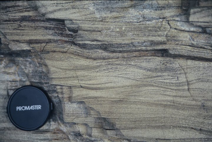
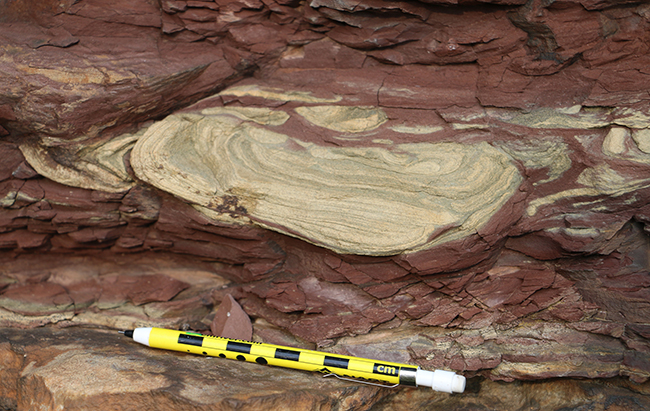
Examine this gigapixel panorama of a specimen of cross-bedded red sandstone. There are two halves to the sample shown. One is right-side-up. The other is up-side-down. Explore the two samples to see if you can figure out which one is which, applying the criteria explained above.
Really large cross-beds form via aeolian (wind) deposition in dune fields. The shape and geopetal implications are the same, but the cross-beds are much larger. Here is an example (right-way-up) from coastal exposures in the western Orkney Islands:
Exceptions to the rule
Cross-bedding can be tricky. Sometimes cross-bed laminae accumulate without the tangential, concave-up portion, and sometimes they preserve the upper convex-up portion at the ripple crest. Even crazier, sometimes the accumuate not on the leeward side of a dune, but the upstream (stoss) side! Let us take a moment to see what these complications look like…
Climbing ripples
Climbing ripples form when downstream migration of a ripple or dune is accompanied by rapid vertical aggradation of sediment. This tends to occur when the sedimentary load is higher than the capacity of the current that’s carrying it. Climbing ripples are distinct structures indicating critical to supercritical flow, but they often look about the same right-side-up as they do up-side-down. The concave-up portion of the laminae in the lee of the ripple is matched by the convex-up crest of the ripple itself, buried as soon as it forms. As a result, they can mislead the historical geologist.
Consider the example below; if you flipped the photo up-side-down, it would be difficult to tell:
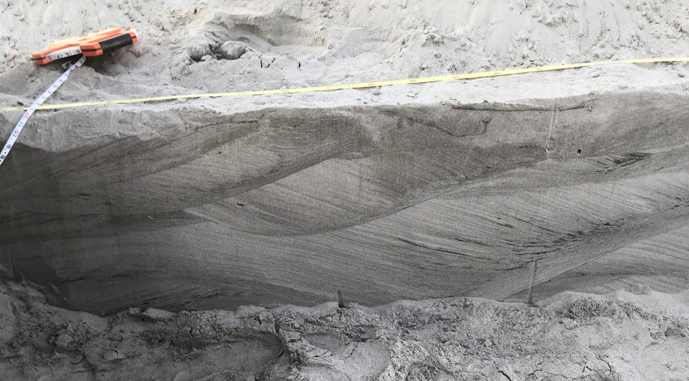
The image at right (click to enlarge) shows a cross-section through three sets of climbing ripples from modern (unlithified) sand deposits in the Mississippi Delta region of Louisiana. Note how the largest, oldest, deepest set of cross beds shows an undulating set of internal laminations, and these “climb” up and to the right, with tangential bases. This is likely indicative of supercritical flow. The second set has a trough-like bottom that cuts into the older set of cross-beds, and is truncated by the most recent, uppermost, thinnest set of cross-beds.
Finally, here is a gigapixel panorama of a specimen showing climbing ripples in cross-section:
Antidunes
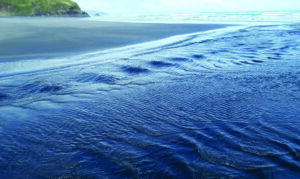
If water is flowing fast enough to be in the upper flow regime, antidunes can form. They are mostly found in shallow channels (e.g., fluvial and tidal channels). If you are lucky enough to see them forming, you can recognize the situation when you see standing surface waves – watch closely and you will see the waves migrate upstream over time, meaning that the are bedforms developing immediately below the standing waves. If high flow is maintained, the antidunes will also migrate upstream. They do this by adding new sediment on their upstream (stoss) side rather than the usual situation for migrating ripples, which deposit sediment on the downstream (lee) side. So antidune cross-beds dip in the opposite direction from normal ripple or dune cross-beds. The good news is that the preservation potential of antidunes is low, because as soon as flow slackens they tend to wash out and be eroded.
Did I get it?
Ripple marks
Ripple marks are the 3D expression of the same phenomenon as cross-bedding: the actual bedform’s shape exposed in lithified form. They can be either symmetrical or asymmetrical. The 3D model below shows a great example of aysmmetric ripple marks, the kind that form in a unidirectional current. Rotate the model so you are looking down the crest of the central ripples so you can see their shape in cross-section: the left side is gently sloped compared to the right side. The left side is therefore the upstream (stoss) side, and the right side is therefore the downstream (leeward) side.
Here is a 3D model showing some ripple marks exposed on multiple bedding planes within the shallow-water Foreknobs Formation (Devonian):
One bedding surface shows fairly linear ridge crests, but an older (deeper) layer to the right shows interference ripples between two perpendicular wave orientations. These create little “point” like features that protrude outward from the bed in the paleo-“up” direction.
Did I get it?
Mud cracks
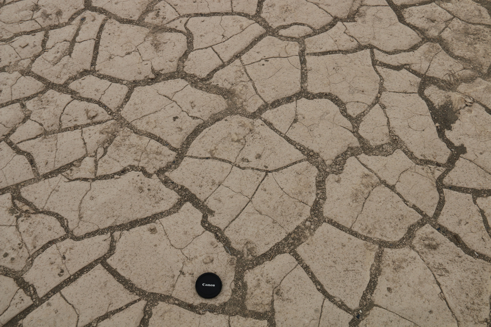
The desiccation of mud produces shrinkage when stresses induced by volume loss through evaporation are greater than the cohesive strength of the mud. Cracks initiate and grow, dividing the mud up into a series of irregular polygons. The photograph here shows the sort of thing we think about when we think of mudcracks: a vast dry field of polygons, sometimes with air between them, and sometimes filled with later sediment.
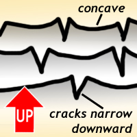
But the geopetal value of mud cracks comes from their cross-sectional view, which is perhaps not as intuitive but is worth considering, because it is very useful. The cracks propagate downward through the mud deposit in an ever-widening gap. This gap is widest at the top and most narrow at its deepest propagating tip, giving it an overall V shape in cross-section. When a deposit of new sediment gets dumped atop this open gap, it can fill it in. In cross-section, this creates a V-shaped projection down through the desiccated muddy layer.
This 3D model shows these aspects of the shape of well-developed desiccation cracks well:
In this gigapixel panorama, you can see a cross-sectional view of some red shale (former mud) and white sandstone (former sand), from the Triassic of Scotland. Note how the mud cracks appear in cross-section: almost like spiky white teeth in a red mouth!
Did I get it?
Graded bedding
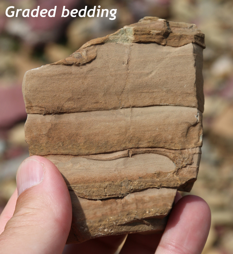
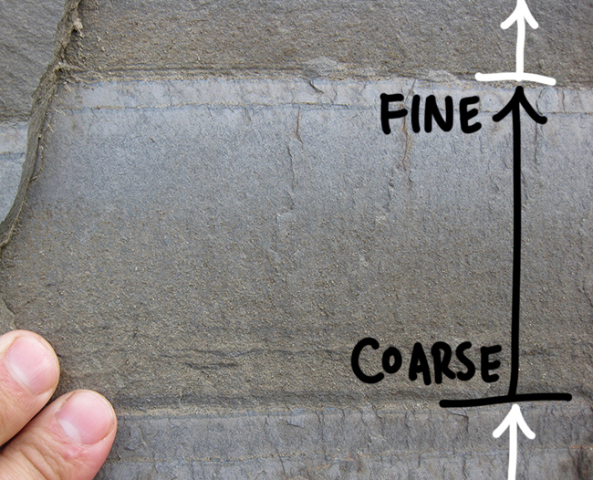
Graded bedding is a distinctive and widespread primary sedimentary structure where the grain size changes systematically from the bottom to the top of a bed. Because graded bedding forms as suspended grains settle from a turbidity current, the heaviest grains tend to settle out first, and those tend to be the biggest grains. A graded bed therefore has the largest grains at the bottom, and then they gradually get finer toward the top of the bed. This change in grain size within the bed is transitional and gradational, but the contact between graded beds will typically be quite crisp – a sudden switch from the fine grains at the top of one graded bed and coarser grains at the bottom of the overlying bed.
Graded bedding is most commonly found in submarine turbidity current deposits (e.g., on an abyssal fan), but it can occur in other settings too, such as lakes, floodplains, and tidal flats.
It also is not limited to siliciclastic rocks, and may be found in carbonate sedimentary deposits as well. In the GIGAmacro image below, you can examine an exquisite sample from the Silurian-aged tidal flat carbonates of the Tonoloway Formation (West Virginia), showing a series of graded beds and corroborating sedimentary structures (annotated in yellow circles) with ambiguous evidence (annotated with pink circles) and misleading evidence (annotated with the lone gray circle). Please click on the various annotations to learn the lessons this sample has to teach about interpreting which way is “up.”
Did I get it?
Exceptions to the rule
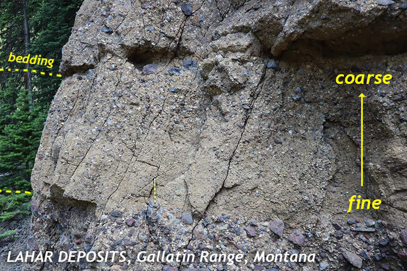
In normal graded bedding, we see coarse at the bottom and fine at the top, with a gradational transition in between. Therefore, in most cases, we can find graded bedding in an outcrop of sedimentary rock or volcanic ash, and find the coarsest bit and head in the direction of the finest bit, and be confident the strata get younger in that direction. However, caveat emptor: nature is vast and varied, and she has a few more tricks up her sleeve.
Reverse grading
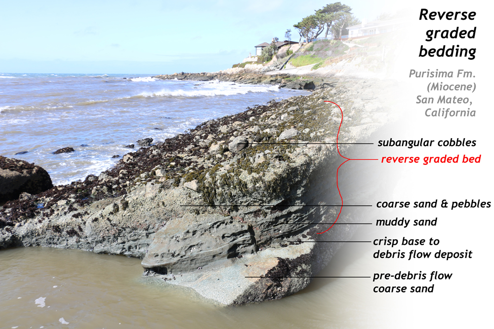
For instance, there are natural examples of what is called “reverse graded bedding,” with exactly the opposite pattern. (It’s also called “inverse graded bedding.”) In particular, debris flows sort grains in the direction that to normal graded bedding would be considered “up-side-down.” In the example at left, we see an example from coastal California: an upright submarine debris flow recorded by a stack of muddy sand transitioning gradationally upward into coarse sand and pebbles, and finally to a surface scum of subangular cobbles. The biggest particles rise to the top due to a phenomenon called “the Brazil Nut Effect.”
Callan Bentley photo.
Recrystallization

Not only that, but metamorphism can make it even more complicated. Consider this example from the Littleton Formation, in the Presidential Range of New Hampshire:
It shows a Devonian-aged turbidite that has undergone serious metamorphism. But not all the minerals in the rock reacted the same way to metamorphic conditions. The clay in the finer, upper part of the graded bed was more susceptible to metamorphic reactions than the quartz making up the sand in the coarser, lower part of the graded bed. As a result, not much happened with the quartz at high temperature and pressure, while the clay reacted profusely to generate huge porphyroblasts of andalusite — crystals many times larger than the grains of sand which were originally the coarsest components of the rock. So the sense of grading was reversed through metamorphic reactions. The key thing to recognizing this phenomena is to understand that the fine portion of a siliciclastic graded bed is likely made of different minerals (clay) than the coarse portion (quartz and perhaps feldspar) and so will show a different susceptibility to metamorphism under high pressure / temperature conditions.
This isn’t a fatal flaw, since we understand the metamorphic reactions that convert clay into metamorphic minerals such as garnet, staurolite, sillimanite, kyanite, and andalusite, and we know that quartz is chemically stable over a wide range of temperature and pressure conditions. In fact, we could consider this a blessing in disguise – because we get information both about the metamorphic conditions the rock experienced (andalusite only forms at low pressures and moderate temperatures) but we also still preserve the crisp/gradational/crisp character of the original graded beds. The primary sedimentary structure is altered, but not beyond recognition. It is not destroyed.
Did I get it?
Recap graded beds as way-up indicators with this slideshow:


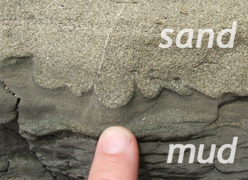
Loading structures
Loading structures form due to density inversions, when heavy wet sand is deposited suddenly atop squishy waterlogged mud. The sand sags downward in broad lobes, and the mud squirts out of the way between those lobes. Once lithified, these bulging sandy lobes and pointy shale fingers serve as excellent way-up indicators. They are best viewed in cross-section, as seen here.
Ball & pillow
We call the sandy lobes that are broad and curved “ball & pillow.” These lumps make blob-like shapes that bulge downward, pointing toward gravity’s paleo-pull direction. They are lobate in form: convex downward, and concave upward. Any internal structures within the sand body, such as laminations or crossbeds, are likewise distorted downward most in the middle and least at the edges, resulting in a “smiley face” appearance in cross-section.
Here is a 3D model of some ball & pillow that formed in Devonian-aged redbeds of the Hampshire Formation [LINK TO ACADIAN CASE STUDY] in the Valley & Ridge province of West Virginia, when a thick layer of sand (today sandstone) was laid down atop a squishy layer of waterlogged mud (today red shale):
Flame structures are what results when the mud squirts out of the way of the intrusion of the sagging sand lobes from above. It forms cuspate features that somewhat resemble flames, poking upward between the ball & pillow structures.
Did I get it?
Sole structures
Sole structures are erosional features formed along the sedimentary interface by powerful currents that then deposit a bed atop their erosional divots and carvings. They include flutes, tool marks, scours, and gutters. All share in common their mode of formation: (1) there must be a pre-existing sedimentary substrate, which (2) gets eroded, making a hole or depression, and then (3) the hole gets filled in with an overlying deposit of sediment. Most all sole structures are preserved not as their original negative shape (a hole) but as the positive shape that results when that hole is filled (a cast). Let’s examine this relationship in the context of flute marks first.
Flutes & flute casts
Often the erosion takes place on/in a substrate of mud (a calm-water deposit), when current energy later increases. The increased current cuts into the soft mud, but also brings in sand (a coarser sized particle). As current energy wanes, the sand is deposited atop the mud, including in the new holes and grooves, making “casts” of them. Much later, when the sediment has all been lithified and the rock has been uplifted to Earth’s surface, the two different rock types react differently to weathering. The mud has turned to shale, which rapidly degrades and falls apart. But the sand has turned to sandstone, which typically stands up much more sturdily to the forces of weathering. It resists degradation. The result is that we typically find the bulging cast rather than the original concavity that was eroded out as a hole.
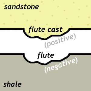
One way of describing the situation is like this: the scour is a “negative” space (a hole), while the cast is a “positive” feature, poking out as a bulge or bump. Whether we’re lucky enough to see the original flute, or only the secondary cast of that flute, the relationship is plain. Negative spaces are cut into the paleo-“down” direction, and their infilling (the cast) mimics this same direction.
Because both the concave-up flutes and their convex-down casts bulge in the direction of paleo-“down,” they are useful as way-up indicators.
Here is a 3D model of flute casts, showing the underside of the sand bed that filled in the original flute:
 Close-spaced flute casts in an Eocene shelf sandstone; flow direction indicated with blue arrow.


Tool marks
Tool marks form when hard objects such as cobbles, bones, wood, or shells get bounced along the bottom of a body of water, carried along by a forceful current. As the object bangs, crashes, drags, and bounces, it leaves behind a series of scratches and divots in the pre-existing sedimentary substrate. Later, these holes can be filled in with subsequent deposits, lithified, and preserved in the geologic record.
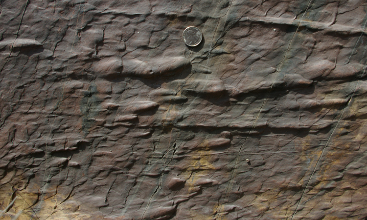
Tool marks (and casts thereof) are similar to flutes in their way-up implications: they project downward into the pre-existing sedimentary substrate, and when they are filled in by subsequent deposition, their shape is preserved as a cast on the bottom of the overlying bed. Here is an example, looking “up” at vertical Spray River Group siliciclastic strata from “below.” As such, the tool marks project off the bottom of the bed, toward our viewing perspective:
Did I get it?
Trace fossils
A similar logic applies to burrows, the holes dug by organisms into sedimentary substrates. An animal can only dig a hole in the mud if the mud is already there to dig in. The hole cannot precede the material into which the hole is dug. So open burrows that are later filled in with contrasting sediment can also serve as a geopetal indicator. Consider the example at right.
Similar, plants cannot take root in soil that isn’t yet there, so root traces also must penetrated in the paleo-“down” direction, at least in the most broad view. Once roots get deep enough, they can of course grow laterally or even upward in addition to growing downward.
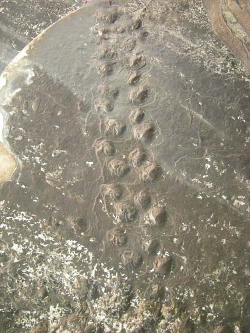
The same idea applies to footprints, which can only press downward into extant sediment, not push upward into sedimentary deposits that haven’t yet been deposited. There are thousands of examples, but let’s consider two here: Consider the images below.
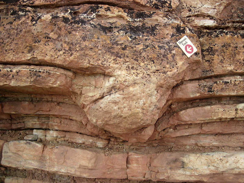 |
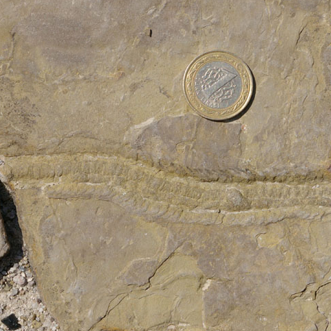 |
One image shows a side-view of a sauropod dinosaur track in disrupting sandstone and shale layers. The other photo shows the sinuous trackway left by some kind of invertebrate in silt, looking down on the bedding plane. We have two different perspectives here, and two different organisms, but what is in common to these bedding-surface traces is that they push/erode down into the pre-existing sedimentary substrate.
Here is a 3D model of the enigmatic Cambrian trace fossil Climactichnites, on display on a wall of a museum at the University of Wisconsin:
The opposite is true here:
Here, in a Permian-aged reptile trackway from the Grand Canyon, the footprints poke upward from the surface of the slab of rock, implying that this is a cast of the reptile’s footprints, not the original divots pushed downward into the sediment.
Whether a monster ancient slug or a more familiar reptile, all organisms leave tracks that push downward into the sedimentary substrate over which they move. As with sole structures, the concave ‘negative space’ pokes downward into the older sedimentary layer, and the infilling creates a convex ‘positive space’ feature that projects downward off the bottom of the younger sedimentary layer.
Did I get it?
Stromatolites

Stromatolites are layered microbial mats, common in Precambrian shallow-water sediments, particularly carbonates, but also sometimes siliciclastic sediments or even banded iron formations. Their photosynthetic life habit causes them to grow upward toward the sunlight, giving them convex-upward (dome-like) shapes. If concave-up instead, they can be interpreted to be up-side-down.
Here is a gigapixel panorama of an outcrop of stromatolites in Banff National Park, Alberta. Explore it to get a sense of their shape when right-side-up:
Here is a 3D model of a stromatolite, from the Mesoproterozoic Belt Supergroup of Montana. Rotate it around to get a sense of how the cross-sectional views on each side relate to the 3D dome-like structure of the fossil (visible on top):
Microbial mats can take on many shapes and textures, but this upward-doming shape of stromatolites is a reliable way-up indicator, especially when there are many individual stromatolites all pointing the same direction.
Test your identification of stromatolite younging direction with this self-quiz:
Did I get it?
Igneous way-up structures
Next up, we will consider the handful of igneous way-up structures. There are not as many as there are in sedimentary rocks, but though few in number, they can come in handy in deformed terranes with igneous strata or intrusions.
Vesicle concentration
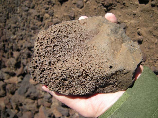
In lava flows that have significant gas content, bubbles (vesicles) form as the lava degases upon eruption. These bubbles have low density, and so want to rise to the top of the fluid flow. Given a sufficiently runny lava, they can make their way upward, accumulating beneath the upper cooling crust of the flow. This creates a concentration of vesicles at the top of of flow, and more massive fine-grained textures at the base of the flow.
Caveat: Lava flows are dynamic systems, and pulsing currents of lava and differential cooling can mix up the vesicle-rich portions and vesicle-free portions. Search for other clues which corroborate the vesicles’ way-up implications.
Apophyses
Apophyses are small injection features, like small dikes, that protrude out from a lava flow or sill into surrounding pre-existing rocks. In a lava flow, they can only project downward, but in a sill they can project both upward and downward. Therefore, to use apophyses as a way-up indicator, a necessary first step is to verify that the apophyses are coming off a lava flow, not an intrusive sill. The
Post-igneous sedimentary strata laid down atop a lava flow may show their own “apophyses” as cracks in the top of the lava flow are filled in with sediment. Below is a cartoon summary of the nature of apophyses for telling sills from lava flows, and telling if lava flows are right-side-up or not:
Pillow lavas

When lava erupts underwater, lava pillows form. On the outside, they have a shape like toothpaste extruded from a toothpaste tube. In cross-section, they show a glassy outer rind and fine-grained (aphanitic) interior, often with radial fractures. As a freshly formed pillow, with its still-molten interior, flows and settles into the submarine topography of older pillows, it often sags a bit in the middle, producing a little downward “pooch.” It looks something like an up-side-down teardrop shape, or a “word bubble” in a comic strip.
Bear in mind that the eruption of lava underwater is a messy process, and a variety of 3D pillow shapes can be produced. Further complications arise when we view these 3D shapes in 2D outcrops, as cross-sectional views. Many pillows are just round or cylindrical, but enough pillows show this distinctive shape that in a decent outcrop, there should be enough that you can figure out the younging direction. Sometimes, they will show more than one downward projection.
In this video, geologist Christie Rowe shows an outcrop of pillows near San Francisco, California:
Plutonic grading and cross-bedding
Crazy as it may sound, the dynamics inside a cooling pluton can mimic some of the same situations we observe at the surface with sediments deposited in flowing water. These include cross-bedding formed by magma flowing through a crystal mush, and graded bedding that results as crystals settle out from a cooling magma. The key here is that in a partially crystallized magma chamber, some minerals are more dense than the melt, and others are less dense. Ferromagnesian (mafic) minerals such as olivine and pyroxene are denser than their surroundings, and will sink if given the chance. Plagioclase feldspar is less dense, and so will “float” upward. Because the ferromagnesian minerals are dark, and the plagioclase is almost white in color, this can create visually striking patterns that are as informative as they are beautiful.
Did I get it?
Conclusion
Many of the structures produced in rocks through geological processes do not record information about paleo-“up” direction. But there are a dozen or so “way-up indicators” that occur in sedimentary strata and some igneous rocks that can help the historical geologist infer younging direction with confidence. Knowing these way-up structures is a critical piece of knowledge in the successful interpretation of stratigraphic sequences in deformed terranes.
Further reading
“Way-up structures” on Wikipedia.