
LEARNING OBJECTIVES
After reading this chapter, students should be able to:
- Describe processes related to sedimentary transport and deposition
- Identify common sedimentary structures
- Use sedimentary structures to interpret physical and characteristics of depositional environments
Preamble
Rocks to a geologist are like books and ancient manuscripts are to an historian. Rocks contain a record of past events and places. The rock record is incomplete. So part of the puzzle is to also try and figure out what is missing. Is it time? Is it other rocks that have since disappeared or perhaps been moved to another location? These are the scientific puzzles that motivate geologists.
The formation of sediment and sedimentary rock involves many physical, chemical and biological processes, sometimes operating separately but more commonly in concert. The journey from loose sediment to hammer-ringing rock is one of the marvels of the geological world. Deciphering this journey requires us to delve into the rock record.
Imagine that a local geologist tells you that the rocks in your backyard were originally deposited as sand and mud in shallow seas, where beaches and broad coastal tidal flats passed seawards to deeper waters, and landwards to marshes and scrubby coastal plains across which rivers and streams coursed. How did our geologist figure this out? What is it that geologists see in the rocks that helps them paint this picture of a world that existed so many millions of years ago?
Tools at a geologist’s disposal
Sedimentary rocks, whether terrigenous, carbonate, chemical, or volcaniclastic, contain a wealth of information that relate how they formed at or close to Earth’s surface, and the various physical and chemical processes that affected them as they were buried. This article deals with the first part of the journey:
-
- How sediment moves across a substrate,
- The language of bedforms,
- The hydrodynamic significance of bedforms, and
- An atlas of common sedimentary structures
Transport of sediment; bedload and suspension load
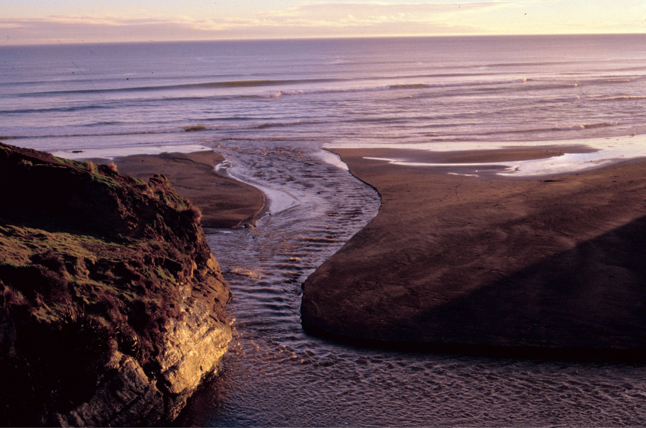
Brian Ricketts photo.
Movement of sediment creates beds, structures within beds (e.g., laminations, crossbedding), and entire depositional systems like deltas and submarine fans. The processes by which sediment moves determine what the deposit will look like: a train of ripples, turbidites, a layer of mud, or Martian sand dunes.
In this section we will examine four of these processes:
-
- The case where a fluid, (water, air) interacts with a bed of loose sand – i.e., bedload transport;
- Where sediment accumulates from a suspension of water and fine particles, and;
- Movement of sediment by surface waves;
- Bedforms in relation to fluid flow – the flow regime.
Bedload
As the name suggests, this element of sediment movement consists of loose, granular particles at the sediment-water interface (such as a stream bed or tidal flat): in other words, at the top of a bed. Air or water that moves across the bed will begin to move grains if the flow velocity is great enough to overcome the force of gravity and any resistance at grain contacts. This is the threshold velocity.
The bedload contains two main components:
-
- the traction load, or traction “carpet,” and
- the saltation load.
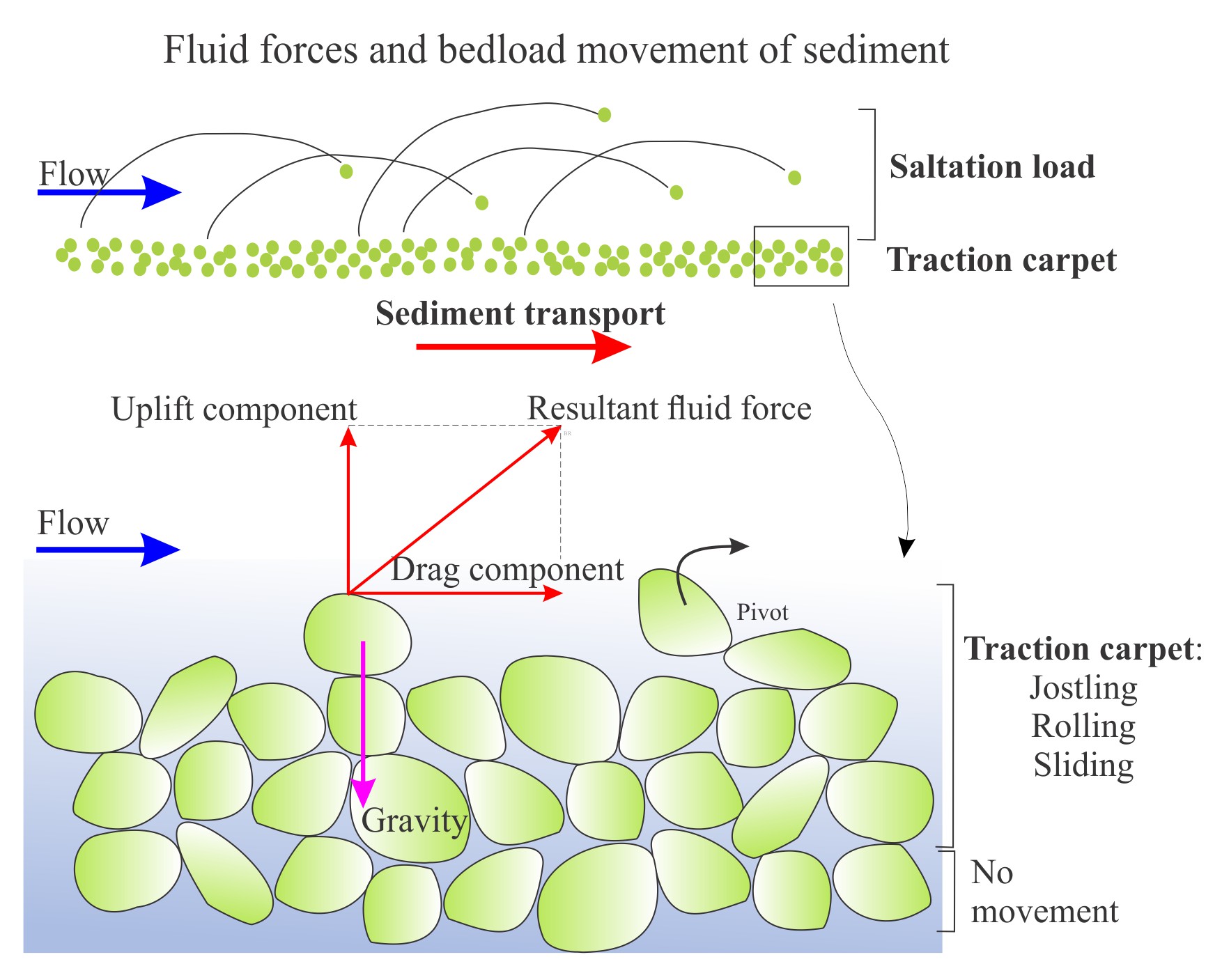
Brian Ricketts diagram.
The various components of force involved in initiation of grain movement are shown here. Fluid flowing over a sediment bed produces shear stresses that can be resolved into a component of drag (parallel to the bed) and a lift component (perpendicular to the bed). At the threshold velocity when the resultant fluid force on grains becomes greater than gravity, grains begin to roll, slide and jostle along the bed like a moving carpet – the traction carpet.
The short video is of wind ripples where sand moves in a traction carpet (viewed best in full screen).
As flow velocities increase, so too will the lift component of fluid forces and grains may temporarily leave the traction carpet, bouncing along with the flow; this process is called saltation. The saltation load is included in bedload because grain excursions into the fluid do not last long. Saltating grains tend to travel much farther in air than water because the contrast in density between the grain and the fluid is much greater. Stand on any sandy beach on a blustery day and you will witness first-hand the effects of grain saltation. Saltation produces many collisions, and not just against your bare legs. Saltation collisions also result in grain abrasion.
The short video shows a saltation load across a windy, black sand beach (sand consists of magnetite, ilmenite and pyroxenes). Saltation also tends to winnow the lighter pyroxenes, separating them from the denser iron oxides.
The ease with which grains move also depends on their density and shape. Quartz grains will move more easily than heavier minerals of the same size. Because they are shaped like little hang-gliders, platy grains like micas, even though they are denser than quartz, will tend to respond hydraulically as lighter particles.

The Hjulström curve plots two domains: the erosion curve shows the critical flow velocity required to move a sedimentary particle across a bed, and the deposition curve the flow velocity at which the particle will be deposited (cease to move). Both scales are logarithmic. For reference, the common size range for sand is 0.0625 mm to 2 mm, highlighted in yellow.
In considering these processes, we also neglect grain cohesion. For most sand and silt-sized particles, cohesive forces will be negligible. This is not the case in fine-grained sediment that contains clay. In this situation, clay particles tend to adhere to each other because of electrical charges on the surface of their crystal structures. Once clays have been deposited, it is difficult to remobilize them as individual particles because of electrically induced cohesion. When erosion does occur, it tends to produce lumps of clay, also referred to as rip-up clasts.
The suspension load
Most natural flows in rivers, shallow marine settings and air are turbulent. Even at low-flow velocities, the speed and trajectories of flow can vary considerably. Even seemingly tranquil streams show turbulent eddies and boils on their surface. Very fine particulate sediment (particularly particles of clay) can be kept in suspension for long periods by turbulence; the stresses generated by turbulent flow balance or overcome the gravitational force acting on the particles.
If turbulence decreases significantly, for example when a river empties into a lake, then most particles will gradually settle to the sediment bed. The rate at which a particle settles out of suspension is called the settling velocity, where the force of gravity (downwards) exceeds the combined effects of upward-directed buoyancy forces acting on a grain and the drag on a particle caused by fluid (viscous) resistance. Thus, the rate of settling depends on the size, shape and density of particles, and the viscosity of the surrounding fluid. In general, settling through air is much more rapid than through water.
Both bedload and suspension load are important processes in the generation of sedimentary structures. In particular, bedload transport of loose sand is the critical process for growth of bedforms and their internal cross-stratification (crossbedding). The description of bedforms (crossbeds) and the flow conditions (flow regime) under which they form are described in following section.
Surface waves
Sea and lake surface waves are generated by wind. The wind provides the energy which is transferred to surface waters. As a general rule, the stronger the wind, the greater the wave amplitude, wavelength, and speed. Surface waves are basically pulses of energy. As such, a water mass does not move in concert with the wave. Instead, water particles beneath waves have a circular or elliptical motion (referred to as an orbital). The largest orbitals occur immediately below the wave crest, decreasing in size to a depth that equates to about half the wavelength. This depth where wave action ceases is called the wave base (or wavebase). If the wave base is deeper than the sea floor, then the waves will interact with the sediment there. Conversely, in deep water, the seafloor sediment is beyond the reach of the wave base, and so waves do not interact with the sea floor.

In normal weather, the wave base is at a given depth, though that actual depth from place to place is variable, depending on wave amplitude, prevailing wind direction and speed, and the shape of the coastline. But during storms, there is more energy transferred from the wind to the sea surface, and so the waves are larger, and wave base is pushed deeper, where it may be able to interact with sediment that was previously “out of reach.”
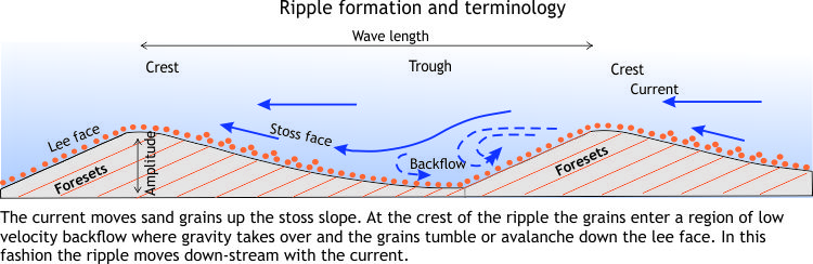
Landward of wave base, the orbitals move sediment and generate bedforms, most commonly symmetric ripples where the lee and stoss faces have similar inclinations (because of the back-and-forth action of wave orbitals).
As waves approach a beach some of the energy is transferred to sediment on the sea floor, wave speed decreases (because of friction and loss of momentum),and wave amplitude increases. At a certain amplitude, waves become unstable and break; breaking waves transfer the water as a turbulent, aerated mass that rushes up the beach (swash) and then recedes (backwash), and in the process stirs surface sediment across the breaker zone and beach.
Crossbedding – Some common terminology
Crossbeds are nearly ubiquitous in sedimentary rocks. They can be found on the deep ocean floor, the driest desert, and pretty well any depositional environment in between. They are most common in sandy deposits. They are less common —but no less important— in gravels (e.g., low sinuosity settings such as braided rivers). Crossbeds form where air and water flow across a bed of loose sediment, so long as the individual sediment grains have low cohesion between the particles: in other words, they are not “sticky.” Mud crossbeds are rare because individual clay particles tend to stick to one another (a result of the electrical charges on the surface of these tiny grains).

Crossbeds in the rock record are visible in bed cross-sections, or as exhumed 3D ripples and dunes on exposed bedding planes. The term crossbed refers to their internal structure; i.e., laminations that are usually inclined in the down-flow, or down-stream direction. Crossbeds are therefore useful in interpreting paleocurrent flow direction. Because the laminations often show a tangential relationship to the main bed at the bottom of the main bed and a truncated relationship at the top, they are also useful as geopetal (“way-up“) indicators.
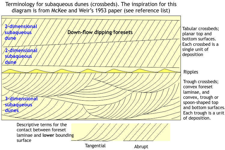
The inspiration for this Brian Ricketts diagram is from McKee and Weir, 1953.
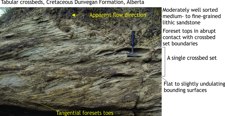
The laminae are called foresets. In a 2D cross-section view, a single crossbed consists of any number of foresets bound above and below by flat or curved boundaries. The geometrical arrangement of foresets, their bounding surfaces and their size or amplitude gives us the information needed to decipher:
-
- the kind of crossbed,
- the hydraulic conditions under which the crossbed formed, and to some extent
- the paleoenvironment in which they formed; keep in mind that most crossbeds can be found in a range of paleoenvironments but used in conjunction with other criteria such as body and trace fossils, sediment composition and stratigraphic trends (e.g., fining upward) will help pin-point specific depositional settings.
Our interpretations can be advanced further if we are lucky enough to see exhumed structures on bedding, such that we can define:
-
- the shape of the ripple or dune crest line (is it straight or sinuous?),
- the wavelength between successive ripple or dunes, and
- a relatively unambiguous measure of ripple-dune migration across the bed (i.e., paleocurrents).
Most of our knowledge about ripples and dunes (collectively referred to as bedforms) and how they form has been garnered from studies of modern environments. After all, if on your walks across a tidal flat or open-air dune field you see ripples that look identical to those preserved in rocks, it is quite reasonable to infer that the ancient bedforms developed in ways similar to the modern analogues (this is the Uniformitarian Principle at work).
In fact, they have also been seen and recorded forming in real time on Mars.
Brian Ricketts photo
The hydrodynamic significance of bedforms – Flow Regime
In this section we introduce some basic hydraulics of sediment movement, bedforms and the concept of Flow Regime.
Ripples and dunes form when a fluid (usually water or air on Earth, but the same concepts apply to lava flows, crystal mushes in a magma chamber, or even the Martian atmosphere) flows across a sediment surface. Structures formed by air flow are called subaerial ripples or dunes; those in water have the qualifier subaqueous. These structures are given the general name bedform. The construction of bedforms requires certain conditions:
-
-
-
- The sand must be cohesionless (i.e., the grains do not stick together).
- Flow across the sediment surface must overcome the forces of gravity and friction, and
- As noted above and illustrated in the Hjulström curve, there is a critical flow velocity at which grain movement will begin; this also depends on the mass of individual grains, and to some extent their shape. For example, flat, platy minerals like mica are easier to move than a grain of quartz with the same volume but a chunkier shape.
-
-
Ripples and dunes form under a relatively limited range of flow conditions. We can illustrate this in a graph of flow velocity against grain size, plotting areas on the graph that correspond to bedform growth. Most of the data for plots like this are derived from experimental flumes where flow conditions can be monitored closely. The plotted distribution shows that bedforms can be categorized according to flow and sediment conditions.
Brian Ricketts diagram.
This partitioning of bedforms was used to construct the Flow Regime hydraulic model, first published in the now classic 1965 paper by J.C. Harms and R.K. Fahnestock and used widely ever since.
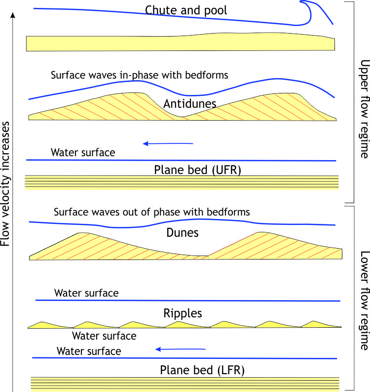
The Flow Regime model considers three fundamentally different states of flow:
-
- No bed movement where there is too little energy in the system to initiate and maintain sand grain movement,
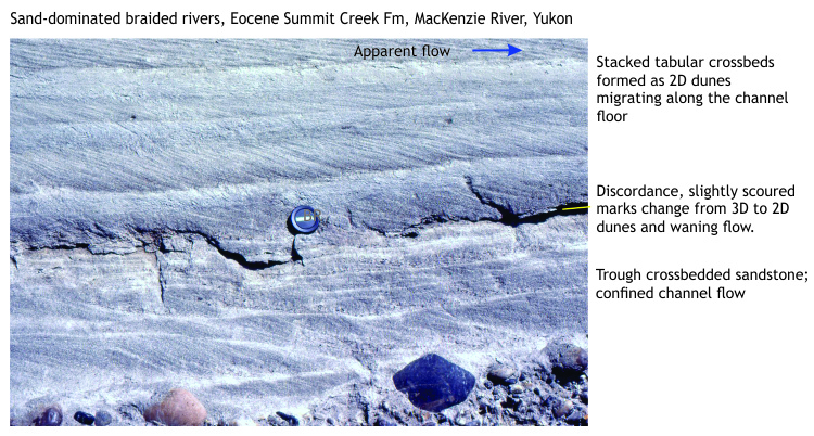
- A Lower Flow regime in which all common bedforms develop. Here, plane bed (basically parallel, planar laminae with no ripples) represents the lowest velocity, or energy conditions where sediment movement is initiated. It has been observed in flumes and in natural channels that the size of bedforms increases from ripples to large subaqueous dunes as flow velocity increases. Dune type also changes from two dimensional structures (straight crests and planar crossbed bounding surfaces), to three dimensional structures that have sinuous, arcuate and lunate outlines and spoon or scour-shaped bounding surfaces (commonly seen as trough crossbeds).
- An Upper Flow Regime where the power of stream flow washes out ripples and dunes, replacing them with plane bed (this kind of plane bed commonly has parting lineations), plus antidunes, and erosional chutes and pools.
- As stream flow increases the transition from Lower to Upper flow regime produces one of the more interesting bedforms – antidunes. They are mostly found in shallow channels (e.g., fluvial and tidal channels). You can recognize that this transition has taken place when you see standing surface waves – watch closely and you will see the waves migrate upstream. Antidunes are the bedforms that develop immediately below standing waves (the two are in-phase). If high flow is maintained, the antidunes will also migrate upstream. However, once flow slackens they tend to wash out. This means that the preservation potential of antidunes is low.
- Hydraulic jumps: The transition from Lower to Upper flow regime passes with a change in bedform, in particular washing out of subaqueous dunes, but there is no sudden break in surface flow – the transition is reasonably smooth. This is not the case for an Upper to Lower flow regime transition that is marked by an abrupt increase in water level and turbulence: a hydraulic jump. Hydraulic jumps can be thought of as standing waves. They are caused by a reduction in Upper Flow Regime velocity, a change in stream-bed gradient or water depth, or combinations of all three.
Brian Ricketts photo.
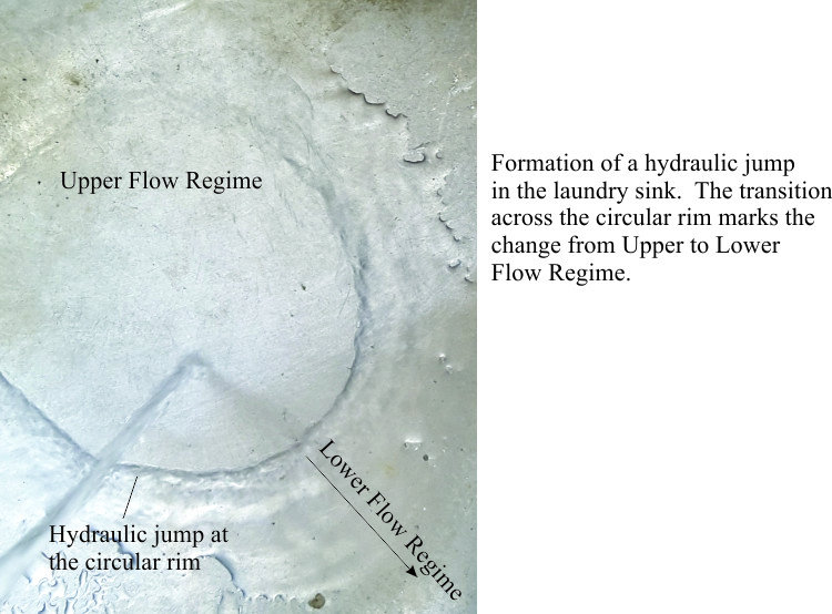
Brian Ricketts photo.
You can generate a hydraulic jump in your kitchen or laundry sink, so long as the sink floor is reasonably flat. Turn on the tap until you see a flow pattern like the one in the photograph at left. Flat laminar flow is generated by the downward force of tap water – this is the plane bed. The hydraulic jump is located at the circular ridge where the flow changes abruptly. Beyond the jump is lower flow regime flow.
We can use the Flow Regime concept in the field as a qualitative indicator of changes in flow conditions with time (i.e., stratigraphically) and space (laterally). For example, a succession of strata that contains a bed of ripples overlain by larger trough crossbeds indicates that flow velocities, and hence stream power increased abruptly. What kind of paleoenvironment could this have occurred in? This is one of the central questions for any sedimentological analysis.
Some common sedimentary structures, their hydraulic significance, and the environments in which they typically are found, are illustrated below.
A short movie of dune-ripple formation
The link here takes you to a short movie of subaqueous dunes forming in a flume (a flume is a narrow tank containing a sand bed, where the velocity of water flow that can be controlled – they are used in experiments to observe the formation of bedforms, and for modelling engineering problems such as the flow of water around bridge foundations). Flow in this experiment is Lower Flow Regime. The sequence begins by showing water flow in front of the migrating lee face; look carefully and you will notice (movie presented by Michael Calzi, SUNY Genseo Dept. of Geological Science):
-
- sand grains being carried along the stoss slope bed;
- when grains reach the dune crest, they avalanche down the lee face – forming crossbed foresets,
- water flow downstream of the lee face appears to flow backwards – this is the backflow shown schematically in the ripple formation diagram above.
Some common sedimentary structures
Identifying sedimentary structures and deciphering how they formed are two of the most important tasks for any sedimentological study. They provide clues, in some situations the only clues, to interpreting ancient environments. The utility of sedimentary structures to unravel the past becomes even more powerful when used in conjunction with other rock properties such as fossil content and geochemistry.
Any examination of sedimentary rocks begins with descriptions of bed geometry, sediment texture, fabric, color and fossil content; sedimentary structures are part of this descriptive vocabulary. Some basic descriptors that are used for outcrop, core or hand sample are listed below.
| Bedding | Thickness |
| Geometry (e.g., parallel bedded, lenticular, lensoidal) | |
| Weathered attributes – is lithology resistant, recessive, cliff-forming? | |
| Color | Note the color; is it uniform, variable? |
| Texture/ Fabric | Grain size – The range of sizes (sorting) |
| Grain size – Maximum clast size (e.g., in conglomerates) | |
| Clast framework e.g. clast-supported, matrix-supported, variable | |
| Clast roundness | |
| Clast angularity | |
| Clast shape (e.g., spherical, platy) | |
| Is there preferred clast orientation (e.g., alignment, imbrication)? | |
| Is there preferred clast distribution (e.g., graded, bimodal) | |
| Sediment/rock classification: e.g., sandstone/grainstone, mudstone/lutite, conglomerate/breccia/rudite | |
| Composition | Begin with the most basic classification: – is it a carbonate, siliciclastic, volcaniclastic? |
| Main clast types: quartz, feldspar, lithics, bioclasts, ooids | |
| Cements: carbonate, silicic, iron oxides | |
| Induration: soft, hard; does it ring when you hit it with a hammer, or make a dull thud? | |
| Fossils | Body fossils, trace fossils, casts or molds? |
| Are there preferred faunal or sedimentary associations? | |
| Shells intact, broken | |
| Have shells been transported or are they in the same position when living? | |
| Relationship to bedding (e.g., infaunal, epifaunal) | |
| Degree of preservation |
In this section, we present examples of:
-
- Bedding
- Crossbedding (cross stratification)
- Structures formed at the soles of beds
- Structures formed by desiccation
- Structures associated with sediment texture and fabric
- Structures formed by sediment gravity flows (mainly turbidites and debris flows)
- Structures formed by deformation and mass movement soon after deposition
- Structures formed by organisms crawling, burrowing, or grazing through sediment in search of food, a place to live, or shelter from predators (these are trace fossils);
- Structures formed by chemical precipitation (evaporites, iron formations, phosphates);
For each structure, or set of structures, there is:
-
- An annotated image from outcrop describing the defining attributes;
- Where possible an annotated image of a modern analogue;
- A brief description of each structure and its formation;
- A list of common depositional environments in which it may be found.
Bedding
Bedding is a sedimentary structure. Sediment moved by currents, or falling from suspension through water or air, will accumulate in a layer, or bed, a process that continues until the supply of sediment is terminated. The plane that defines the top of the bed (bedding plane) represents the termination of that depositional event. Renewed deposition will see the accumulation of a new bed. A bedding plane thus represents a period of time in which no, or very little sediment was deposited – the duration of the hiatus might be minutes, weeks, or centuries.
Common descriptive elements of bedding are listed in the table above. Keep in mind that descriptive words like tabular bedding (where bedding planes are basically parallel), or lenticular (where beds are lens-shaped) depend on the scale of your observations. For example, beds that are tabular at the outcrop scale, may pinch out (as at the outer limits of a lens), or thicken in exposures farther afield. Note too, that outcrop views are commonly two-dimensional, so what appears to be a “tabular” bed may be lenticular in the third dimension (i.e., deeper into the rock beyond the outcrop face).
| Sedimentary structure | Primary attributes | Common environments |
|---|---|---|
 |
Tabular bedding can form in many environments. This example is from a turbidite succession. Beds occur in packages that are also tabular. Can form in almost any sediment type, from conglomerate to mudstone; siliciclastic, carbonate, volcaniclastic. | Almost any marine, lacustrine or terrestrial environment. |
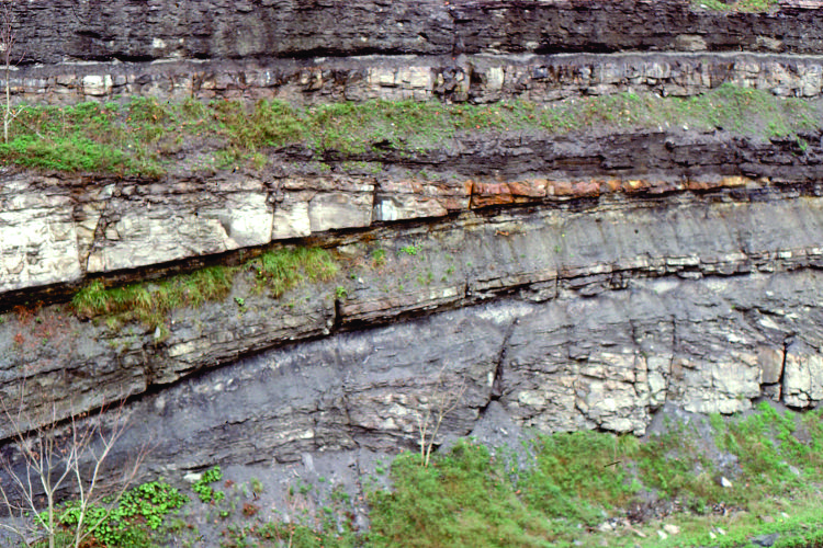 |
Lenticular bedding is common in many environments. This example is from Carboniferous fluvial deposits.It can form in any sediment type, from conglomerate to mudstone; siliciclastic, carbonate, volcaniclastic. | Almost any marine, lacustrine or terrestrial environment. |
 |
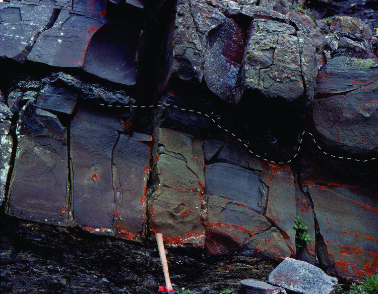
Channelized bedding downcutting the underlying lithology. This example is a fluvial channel that has eroded slightly older floodplain mudrocks. Common in coarse-grained lithologies (sandstone, conglomerate). The lower contact is erosional. | Many kinds of fluvial, tidal flat, estuarine, alluvial fan, delta, and submarine fan channels. |
Crossbedding
Refer to the text and diagrams above for an outline of fundamental processes of crossbed formation, and crossbed terminology.
| Sedimentary structure | Primary attributes | Common environments |
|---|---|---|
|
Tabular crossbeds in a fluvial channel. Each crossbed set has a planar basal contact with foresets tangential to that base. Paleoflow was to the right. Below the lens cap are several trough crossbeds. Each crossbed represents a migrating dune. See the modern examples below. | Common in many marine and terrestrial settings. Diagnostic of the energy of flow rather than any specific environment. |
 |
Tabular crossbeds in a sandy fluvial channel; foreset contacts indicated. Flow was to the left. See the modern examples below. | Common in many marine and terrestrial settings. Diagnostic of the energy of flow rather than any specific environment. |
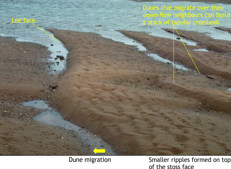 |
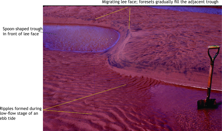
Modern dunes having straight crests are the bedform equivalent of tabular crossbeds. These examples grew during tidal flow on a sandy tidal flat. Small ripples have formed on the stoss slopes of each dune. | These examples formed during successive flood tides. The small ripples formed during subsequent ebb tides. |
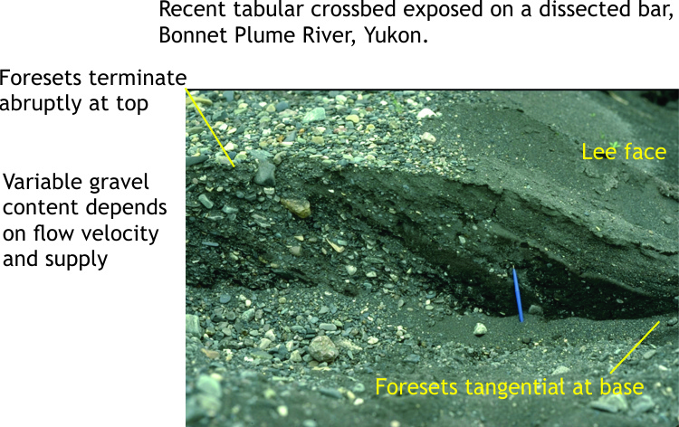 |
Tabular crossbedding revealed in a slice through a dune on an exposed river channel bar. | This example formed during the flood stage in a mixed sand + gravel, braided river channel. Note, this kind of flow is quite different to the tidal flat examples shown above, but the crossbeds look similar. |
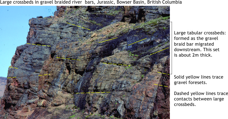 |
Tabular crossbeds up to 2m thick, in this gravelly, braided Jurassic river system. The crossbeds formed as part of large gravel bars within a river channel. | Tabular crossbeds are common components of sand-gravel bars in braided rivers. They commonly occur with trough crossbeds. |
|
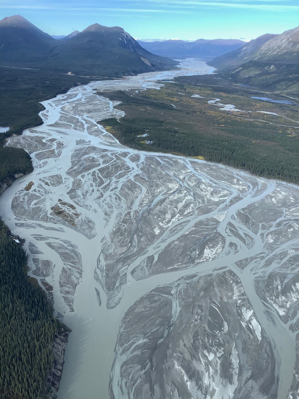
A modern braided river, the Donjek, in the Yukon Territory of Canada. The channel bars consist of sand and gravel – tabular crossbedding is common here.
It’s also worth noting the gray-blue color of the water, indicating a through-going transport of suspended sediment. |
Tabular crossbeds are common in meandering (high sinuosity) and braided (low sinuosity) river channels. |
 |
In 2D exposures, trough crossbeds have convex-up basal contacts; foresets tend to be tangential. Troughs commonly cross-cut earlier-formed structures, resulting in a complex array of partly preserved bedforms. | Common in channelized (confined) flow; found in tidal, estuarine, fluvial, and alluvial fan channels. This example is from an ancient tidal channel. |
 |
Recent dunes on an exposed tidal channel margin, are the 3D equivalent of trough crossbeds. Crest-lines are sinuous. The spoon-shaped troughs are scoured by tidal or stream flows (here covered by water) are filled by the advancing lee faces. Dune migration is to the left. | This example is from the margin of a tidal channel in Minas Basin, Fundy Bay, Nova Scotia. |
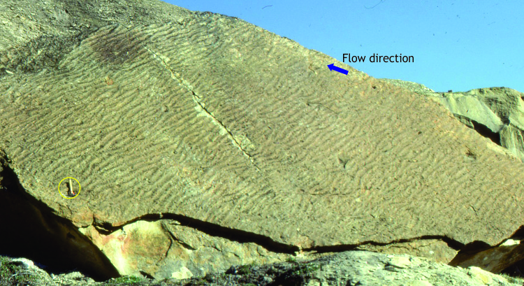 |
Straight crested ripples nicely exposed on bedding. Lee slopes on each ripple consistently face in the direction of the blue arrow. The regularity of ripples indicates consistent flow across this Paleocene tidal flat. | Ripples are one of the most common bedforms, and can form in environments ranging from sand dunes, rivers and alluvial systems, tidal flow on tidal flats, channels, estuaries and continental shelves, and deep ocean basins on submarine fans. |
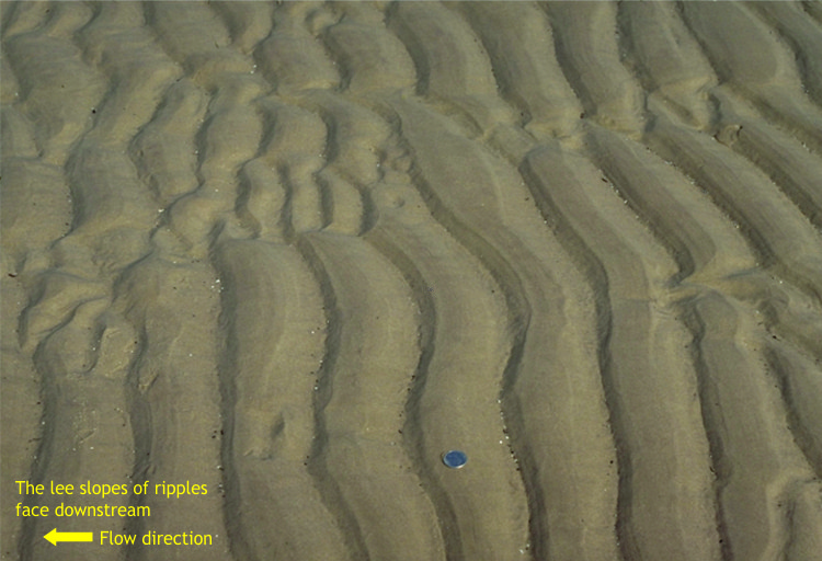 |
Modern straight- to slightly sinuous ripples on a tidal flat. Lee slopes consistently face left in the direction of tidal flow. | |
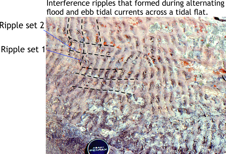 |
Interference ripples contain two distinct sets of ripples at high angles to each other. One set is formed during flood tide and the other during ebb tide. However, distinguishing between flood and ebb is generally not possible unless there is independent evidence for the orientation of a paleoshoreline. |
Common on tidal flats. |
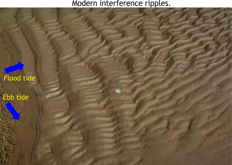 |
Interference ripples. On modern tidal flats we can observe the two ripple sets forming at each stage of tidal flow. |
|
 |
Lenticular and flaser crossbedding; Lenticular crossbedding refers to sand ripples that overlie or are draped by thin mud layers. Mud flasers drape sand ripples or occur in the troughs between ripples. Lenticular ripples dominate in this example from a Pleistocene tidal flat. | Lenticular and flaser crossbedding are good indicators of tidally influenced environments. Both structures indicate the reversal of tidal flows (ebb and flood) and the changing capacity to deposit sediment. |
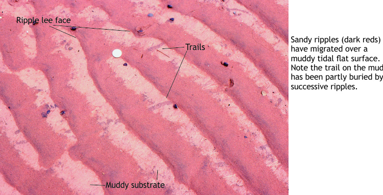 |
A recent example of lenticular ripple crossbedding. Sand ripples (darker reds) overlie a mud layer (lighter colors). The ripples partly overlie invertebrate trails. | Tidal flats, lagoons, estuaries, and shallow subtidal environments. |
 |
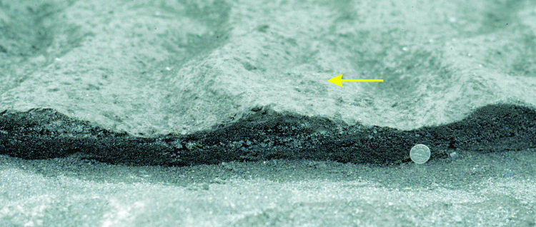
Climbing ripples (also called ripple drift); , Form when bedload transport acts simultaneously with the settling of fine sand from suspension. Successive ripples appear to climb over their predecessors. | Form when there is a high suspension load of fine sediment combined with sediment carried by flowing currents. Can form at the mouths of channels where flow velocities suddenly decrease, and in decelerating turbulent flows such as turbidites. |
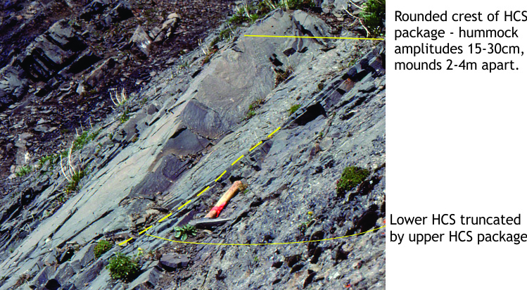 |
Hummocky cross-stratification (HCS) forms at storm wave-base, when sea floor hugging turbulent flows interact with storm wave orbitals. Above storm wave base their preservation potential is low because of reworking by fair-weather wave orbitals. |
HCS is common on open marine, sandy shelves and platforms. |
 |
Another example of hummocky cross-stratification, from Miocene volcaniclastic sandstones from western Costa Rica. | These convex-up scoops filled with half-“smiley faces” make excellent way-up indicators. |
 |
Very large tabular crossbeds in aeolian dunes, this example from the Jurassic Navajo Sandstone, Navajo National Monument. Sets of dune bedding are indicated by black lines. Some sets are more than 10m thick. In most beds, foresets are tangential to the basal contacts. |
Crossbeds are common in aeolian dune seas (ergs) and coastal sand dune complexes. There can be significant variability in crossbed geometry and size. Similar crossbedding is also seen on Mars. |
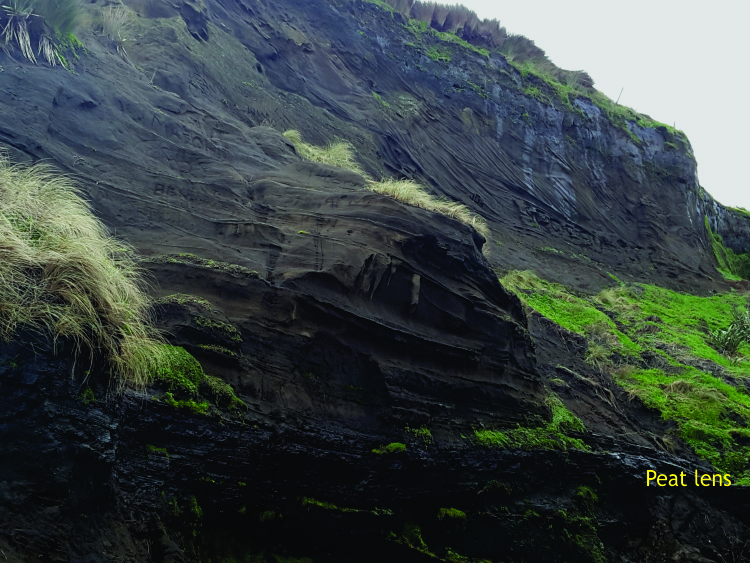 |
Multiple cross-cutting crossbed sets (mostly tabular) in a dissected Pleistocene, coastal dune complex. Prevailing wind was to the right (onshore). The lens of peat at bottom of image (about 50 cm thick) accumulated in a small interdune pond. | Coastal dune deposits will tend to show greater variation in crossbed thickness and lateral extent, and will be interbedded with interdune pond-lake deposits, and deposits from coastal storm incursions. |
 |
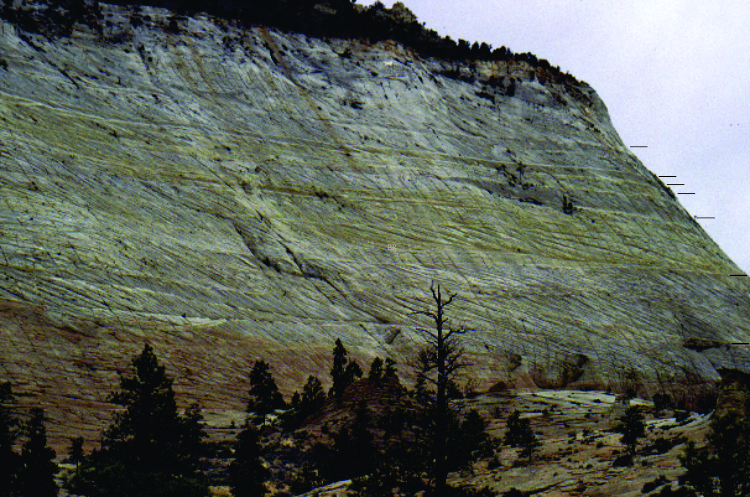
Large-scale dune crossbedding exposed on a cliff of Jurassic Navajo Sandstone in Zion National Park, Utah. The image cycles between a raw photograph and an annotated view, where each of the ~10 principal beds are highlighted with different colors, and the traces of their internal crossbedding traced out with white. | Note the tangential attitude of the cross-beds at the bottom of each bed, and their truncation by the overlying bed. This relationship can serve as a useful geopetal indicator. |
 |
This image from Curiosity Rover shows an advancing lee face of a large dune on Mars. The inset shows a typical dune sand as viewed by Curiosity’s hand lens. |
Aeolian processes are active and widespread on Mars. We can use our knowledge of Earth’s aeolian processes to help us understand these Martian versions. |
Sole Structures
Sole structures are formed during deposition of sediment. The most common types are structures formed by scouring erosion of the substrate by a flowing current, by objects dragged across the sea or lake floor (e.g., bits of wood, shells, or pebbles), and by objects that bounce along the substrate. The depressions thus formed are filled by new sediment such that they are part of the basal contact of the overlying bed – i.e., they are casts of the depressions and are located on the bottom of the overlying bed. As the sole of a shoe is on its underside, sole structures are also formed on the underside of beds. They are sometimes called sole casts. Sole structures are most easily identified on exposed bedding. Flute, groove, and bounce casts are common in turbidites, but can form on shallow continental shelves and platforms, particularly during the passage of storms. Examples include gutter casts, narrow, elongate scours in the sea floor 15-20 cm deep, that form during coastal storm surges.
| Sedimentary structure | Primary attributes | Common environments |
|---|---|---|
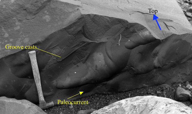 |
Large flute casts at the base of a turbidite bed. Current flow (indicated) determined from flutes is generally unique. The groove casts parallel the flutes but inferred flow is ambiguous. | Flute casts are most commonly observed at the base of turbidites in submarine fan, submarine canyon, and prodelta deposits. |
 |
Close-spaced flute casts in an Eocene shelf sandstone; flow direction indicated. | Flute casts are less common under normal conditions on a shelf or platform, but can form from offshore flow of storm surges. |
 |
A nice collection of skip, groove and flute casts at the base of a turbidite bed. The flutes indicate flow to the right. There are also some load casts, but these formed after deposition was completed. | The utility of flute casts for determining paleoflow directions is nicely illustrated here. |
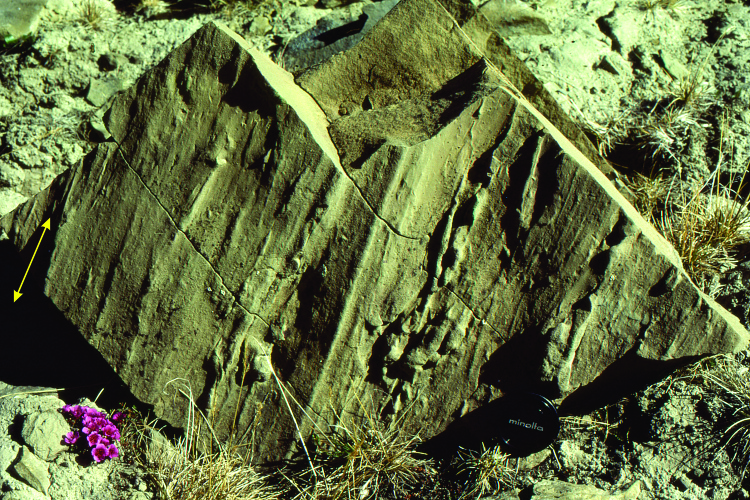 |
Groove casts at the base of a sandstone (shelf environment). Arrow indicates the ambiguity of paleoflow – possible flow directions are 180°apart. |
|
 |
Gutter casts (outlined) in Jurassic shelf sandstone; probably the result of a coastal storm surge. The same bed also has some pebbles and fossil debris that were transported offshore by the surge. | These structures known mainly from shelf and platform deposits, formed by bottom-hugging return flows generated by storm surges. |
Structures formed by desiccation
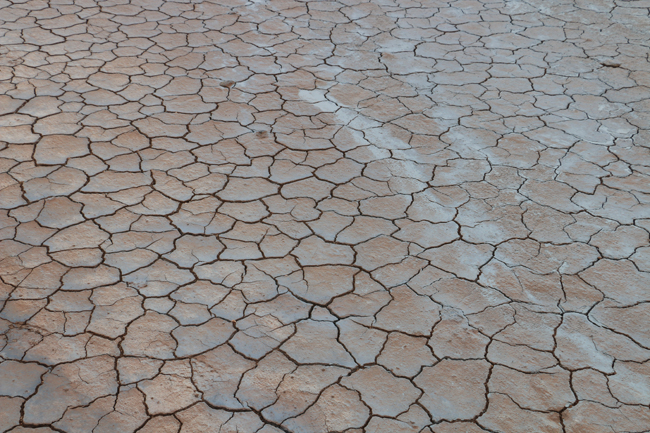
Desiccation means “drying out.” Desiccation of subaerially exposed surface sediment or soil drives off ambient moisture, reducing its volume, and resulting in shrinkage. Shrinkage cracks can extend many centimeters below the surface. Propagation of shrinkage cracks, or mud cracks, across a sediment surface commonly produce 5 and 6-sided polygons. If desiccation continues, the polygon margins will begin to curl upward. Mudcracks are common on river floodplains, the inactive parts of alluvial fans, and supratidal environments that are exposed for long periods. Desiccated sediment is prone to reworking during river flooding, and periodic king tides or storm surges across intertidal and supratidal flats.
Mud cracks preserved in the rock record are excellent indicators of subaerial exposure and may indicate:
-
- falling sea levels,
- changes in the location of river channels and adjacent floodplains,
- arid climate
| Sedimentary structure | Primary attributes | Common environments |
|---|---|---|
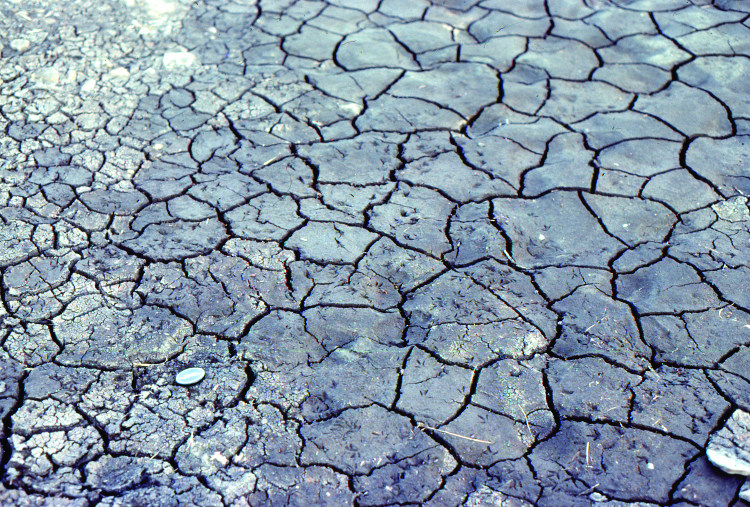 |
Desiccation of river overbank muds has produced 5- and 6-sided polygons, and shrinkage cracks 3-4 cm deep. Some polygon margins exhibit slight curling. | Common in muddy sediment and soils subjected to prolonged exposure: e.g., river floodplains, supratidal parts of tidal flats and lagoons, and terrestrial environments having fluctuating water tables. |
 |
Desiccation polygons in a flat area adjacent to hydrothermal mud pots near the Krafla volcanic center in northeastern Iceland. | |
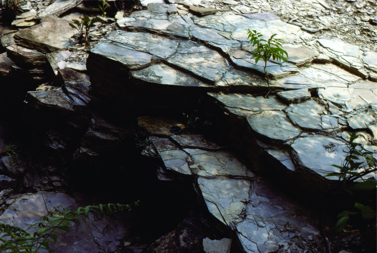 |
Desiccation polygons 10s of cm thick can form by repeated drying of successive mud layers, where the orientation of shrinkage deformation is guided by pre-existing mud cracks. | |
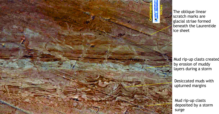 |
Intertidal to supratidal layers of carbonate mud were subjected to prolonged desiccation. Polygon margins are curled upward. Some desiccated layers were eroded by storms, producing abundant mud chips. | Desiccated sediment in supratidal regions is prone to erosion by king tides and storm surges. |
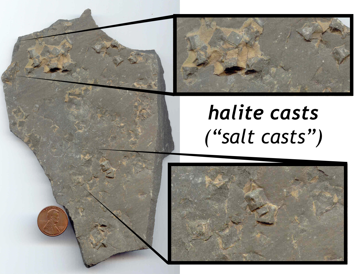
|
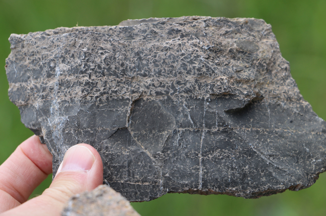
Halite casts can be preserved as 3D cube-shaped forms that protrude from the surface of the bed, as with this slab of Appekunny argillite (Purcell Supergroup, Alberta). | |
 |
Gypsum is another common evaporite mineral whose form can be preserved in shape, even after dissolution and replacement. This photo shows gypsum casts in limestone, Silurian Tonoloway Formation of eastern West Virginia. | |
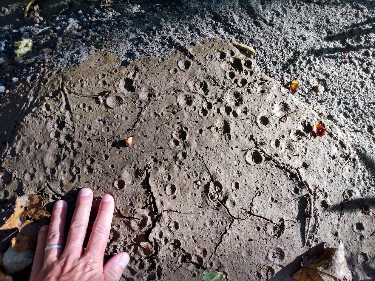 |
Sometimes accompanying the desiccation process will be a brief spatter of rain. Individual raindrops can excavate very well-defined ‘craters’ upon impact with semi-cohesive damp mud. Cross-cutting relationships with mud cracks can help establish relative ages. Modern mud, central Virginia. |
Structures formed by sediment textures and fabrics
This category of structures is based on textural properties of sediments, such as clast shape and orientation. We often think of sedimentary grains as approximating spheres. However, clasts commonly deviate from this ideal shape – they may be blocky, flattened or plate-like, rod-like, or tapered cones (fossil groups such as gastropods commonly conform to the latter shape). During transport in flowing currents (air, water), clasts like these will tend to be aligned according to their most stable hydrodynamic orientation. Identification of preferred clast orientations provides another useful tool for measuring paleoflow directions.
| Sedimentary structure | Primary attributes | Common environments |
|---|---|---|
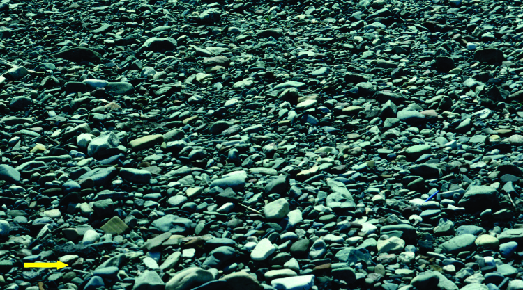 |
Imbrication (preferred alignment) of flat pebbles and cobbles in a recent river channel. The flat clasts are consistently inclined upstream; flow was to the right. | Common in gravelly rivers, particularly braided rivers, but can occur in any channel containing flattened clasts or shells. |
 |
Imbrication of oblong or platy gravel clasts can serve as an indicator of paleo-current flow direction. This example comes from Death Valley, California. | A similar effect can be seen in leaves shed from deciduous trees, as they “shingle up” on on another when washed along by rainstorm currents. |
 |
Current alignment of Permian fusulinids (foraminifera) on bedding. The sense of flow direction is ambiguous in this case, but might be confirmed by other structures in the rocks. | Current alignment of fossils is common in channels, or over broader substrates like the sea floor where strong tidal currents are present. |
 |
Bedding view of parting lineation in laminated sandstone; each parting is one or two grains thick. This fabric develops under Upper Flow Regime Plane Bed conditions. Paleocurrent directions are ambiguous. | Most common in fluvial or tidal channels where high flow velocities are sustained. |
Structures formed by sediment gravity flows
This section contains images and brief descriptions of turbidites and debris flows.
Turbidites are mostly found in deep marine basins and lakes, but are also known to occur in shallow settings like continental shelves. They are deposited from turbulent, bottom-hugging flows of water carrying (mostly) sand and mud. Turbidity currents can travel many tens of kilometers across the sea floor. Turbidity current deposits, called “turbidites,” are the principal components of submarine fans.
The classic descriptive model of a turbidite deposit was developed by Arnold Bouma, and is appropriately called a Bouma Sequence. The sedimentary components of a typical Bouma Sequence are shown below. A Bouma sequence represents a single turbulent flow.
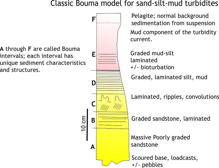 A complete turbidite contains intervals A through E.
A Interval: This interval contains the coarsest sandstones, and may include pebbles or chunks of mudstone that were ripped from the sea floor during passage of the turbulent current – not surprisingly these chunks are called mudstone rip-ups (or “rip-up clasts”). Contact between the A interval and the underlying deposit is abrupt and may be scoured; the scours may be fluted and /or filled with pebbles.
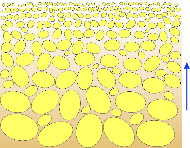
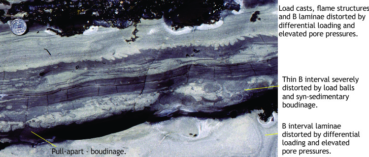
B Interval: The B interval is also sandy, but is distinguished from the A interval by two common attributes: (1) the sandstones are graded (coarser framework grains at the bottom of the interval, becoming finer towards the top), and (2) the sandstones are commonly laminated.
C Interval: Mostly fine-grained muddy sandstone typically containing sandy ripples and climbing ripples, and ripple crossbedding that has been deformed into convoluted patterns (see the examples below).
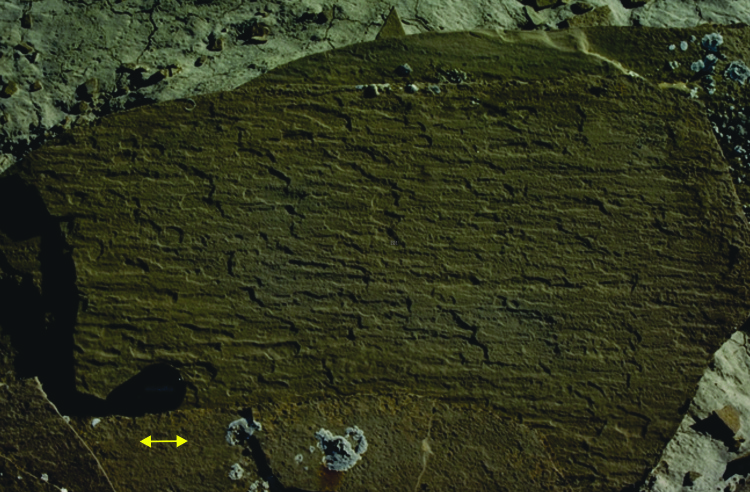
D Interval: Mostly laminated, graded, muddy siltstone. This interval represents the late stages of deposition from the turbidite.
E Interval: This interval contains the mud component of a turbidity current, most of which falls out of suspension from the cloudy plume above the main flow. It is generally mixed with background suspended sediment from the water column above; it can be difficult to distinguish these two sediment components.
F Interval: This interval represents a return to ‘normal’ background sedimentation which in many cases is a mix of pelagic (e.g., skeletal remains of micro-organisms) and suspended particles in the water column (the latter is also referred to as hemipelagic mud).
In thick turbidite successions, it is common to find individual flow units that are incomplete Bouma sequences; thus one flow unit may preserve only A and B interval sands, where others present B, C, D and E, or C, D, and E intervals. Variations like these generally reflect proximity to the source of the turbidity current, as well as the availability of sediment. For example, sandy turbidites containing thick A and B intervals are more likely to be deposited in the proximal parts of submarine fans (i.e., closer to the sediment source and the head of the fan); finer-grained turbidites lacking thick A or B intervals will tend to accumulate in the more distal parts of submarine fans (i.e., further to the sediment source and closer to the outer fringes of the fan).
Debris flows are also mixtures of mud, water, and coarse debris, but unlike turbidites they lack fluid turbulence during flow. The capacity of a debris flow to carry material, including house-sized blocks, lies in the viscosity and mechanical strength of its mud matrix. Debris flows are mobile, commonly destructive phenomena. In terrestrial settings, they can evolve from landslides, aided by high precipitation or snow melt. The equivalent phenomena in volcanic terrains are called lahars – debris flows consisting almost entirely of volcanic debris – that develop both during and after eruptions.
Subaqueous debris flows are commonly generated during slope failures (submarine landslides) that are triggered by seismic events or gravitational instability. Turbidites and debris flows are often found together in the rock record.
| Sedimentary structure | Primary attributes | Common environments |
|---|---|---|
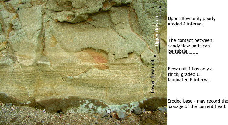 |
Two coarse-grained, sandy turbidite flow units – the low unit has a single, graded B interval; the upper unit begins with a poorly graded A interval (remainder of this unit out of the picture). Contact between the two units is planar. | Thick, coarse-grained turbidites tend to accumulate on the proximal parts of submarine fans. |
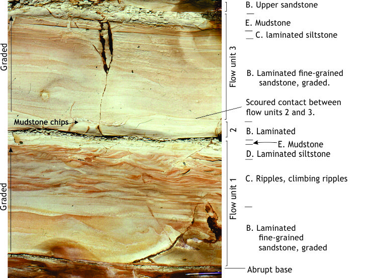 |
Three turbidite flow units: A lower B-C-D-E unit with excellent examples of ripples and climbing ripples in the C interval; a middle B unit, the top of which has been eroded by the upper B-C-D-E unit. Units 1 and 3 are graded. A lag of mudchips formed during scouring of the middle unit. | Probably mid-submarine fan |
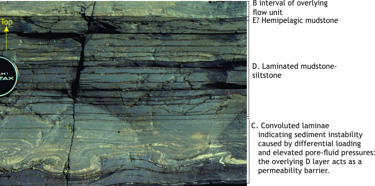 |
A fine-grained, muddy turbidite with well developed C and D intervals. The convoluted bedding (small fold structures) formed after deposition during the early stage of compaction | Mud-dominated turbidites (lacking sand) tend to accumulate on the outer, more distal parts of submarine fans. |
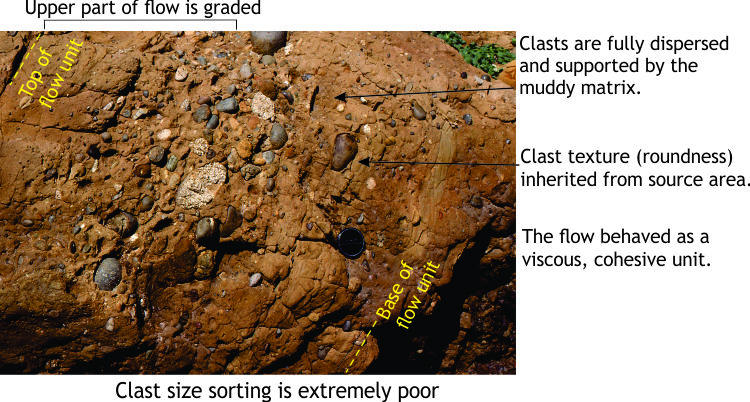 |
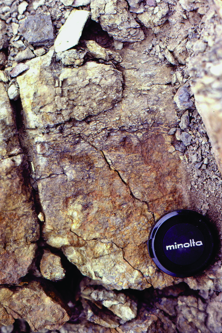
A pebbly mudstone, or muddy debris flow, showing typical high mud content that supported the larger, denser clasts during flow – i.e., a matrix-supported texture, that indicates viscous flows (generally lacking the turbulence of a turbidite). The bed in this images dips to the left. | Commonly associated with turbidites on submarine fans. Can be initiated by collapse of submarine slopes or landslides. |
 |
Good examples of matrix-supported debris flows in the San Onofre breccia. Most clasts here are angular indicating little or no mechanical abrasion during flow. Clasts include glaucophane schist derived from subducted rocks in a nearby metamorphic terrane. | Clasts in debris flows tend to be pebble through boulder size, and are extremely useful for identifying ancient sediment sources (i.e., provenance) |
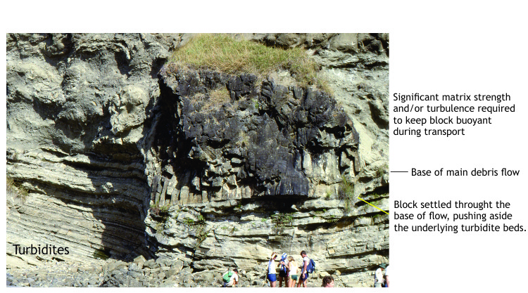 |
An Early Miocene debris flow that carried megablocks – in this case, a large piece of jointed basalt. Clearly demonstrates the mechanical strength of the mud matrix and the mobility of such flows. | |
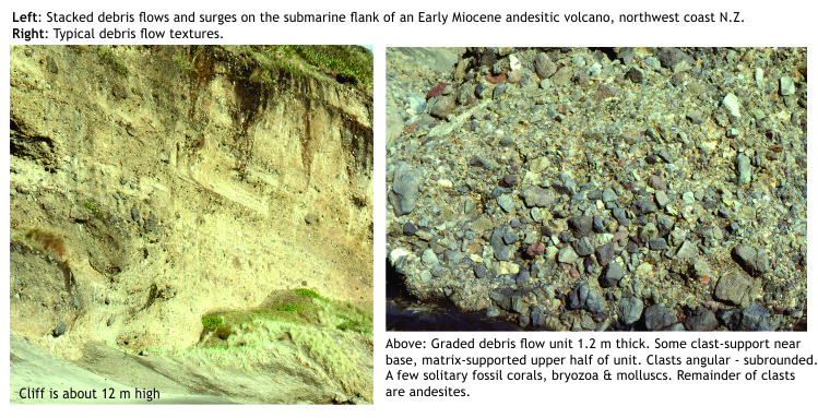 |
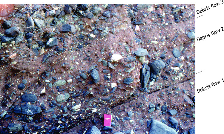
A succession of submarine debris flows initiated on the submerged flanks of early Miocene volcanoes. Image right shows typical textural variations: very poor sorting, a range in clast shapes, and variable clast supporting characteristics ranging from matrix- to clast-supported. | The general category of debris flows includes lahars – flows generated on the subaerial or submerged flanks of volcanoes, and consisting of volcanic debris. |
Structures formed by mass movement (MTDs)
Mass Transport Deposits, or MTDs, is the term given to sedimentary slumps and slides, mostly generated on relatively high-angle slopes between the shelf or platform margin, and deep-water settings at the base-of-slope and beyond. The term is generally reserved for sediment packages that move and deform en masse under the influence of gravity.
There is a close association between MTDs and autochthonous (undisturbed) muddy slope deposits, and turbidites in submarine fans. MTD packages commonly overlie undisturbed turbidite assemblages, and in turn are overlain or draped by non-deformed strata. The slumps, and slides themselves generally consist of deformed turbidites and related deposits.
MTDs develop via a range of emplacement mechanisms and mechanical processes; most sediments will be ‘soft’, unconsolidated or only mildly so, and have high interstitial fluid contents (usually seawater). Sedimentary layers may bend and fold, or break like brittle materials. Liquefaction is also common where sediment becomes fluid-like. All these mechanisms may occur in the same structure. The deforming slump or slide package may also generate debris flows and turbidites.
| Sedimentary structure | Primary attributes | Common environments |
|---|---|---|
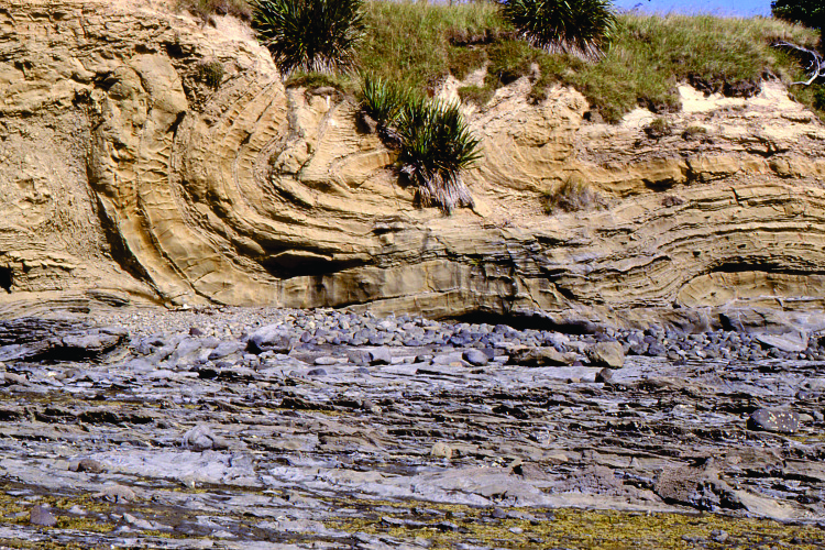 |
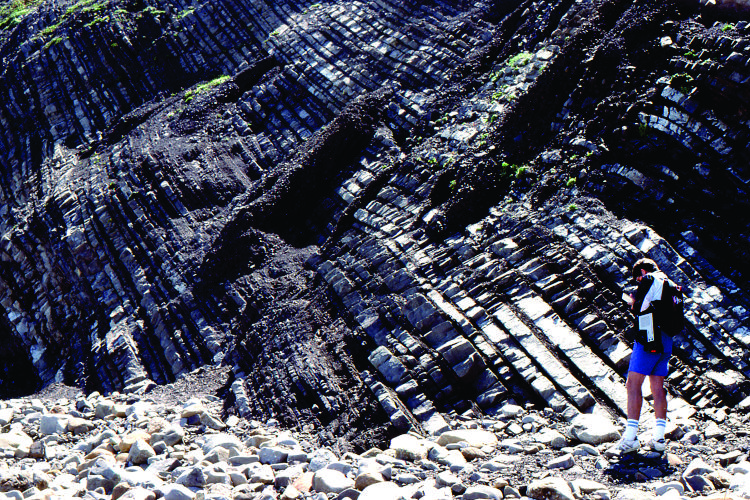
Turbidite beds, while still relatively soft, have been folded and overturned into a recumbent anticline. This structure is part of a much larger package of deformed strata that moved down the ancient Miocene submarine slope | Most common in continental slope and deeper basin environments, associated with submarine fans. |
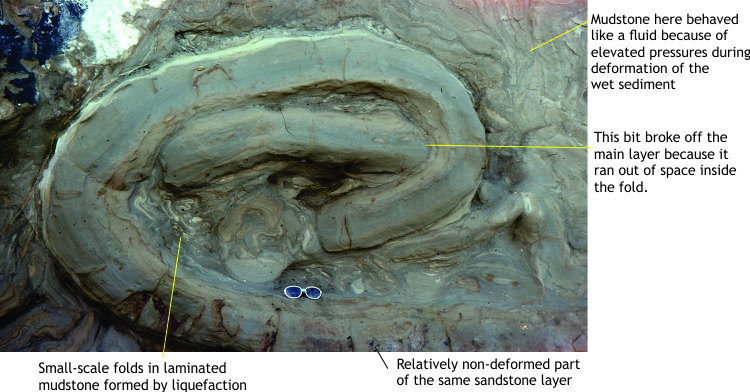 |
A smaller-scale folded and faulted sandstone bed within a succession of turbidites. Folding and sliding of soft sediment also formed small faults, and squishing of water-logged that liquefied the muddy sediment. Early Miocene, Auckland. | Deformation of soft sediment can involve brittle failure (small faults), plastic-like folding, and flow from liquefied sediment |
 |
The slump package, or MTD, (Miocene, Auckland) is separated from undeformed turbidites by a relatively smooth glide plane (a plane of movement). The MTD is bound on the right by a fault – the fault terminates at the glide plane. The fault formed during the slumping and deformation event. | MTDs commonly overlie undeformed strata, separated by a planar surface that is also undeformed. |
 |
Large-scale folds and faults in Pliocene turbidites, Ridge Basin, California. Some of this deformation may have been triggered by seismic activity on the ancestral San Andreas fault. | Slumping and sliding can be triggered by oversteepening of the sea floor as sediment accumulates (gravitational), by seismic events, or large storm surges. |
 |
Small-scale folds and breakage of thin beds of carbonate mudstone (lutite). This example formed in lime mudstones on a slope adjacent to a Paleoproterozoic carbonate platform (Belcher Islands). | Sedimentary slumps and slides can occur in siliciclastic, carbonate, and volcaniclastic deposits |
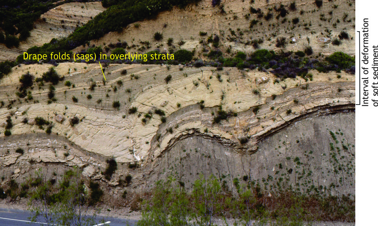
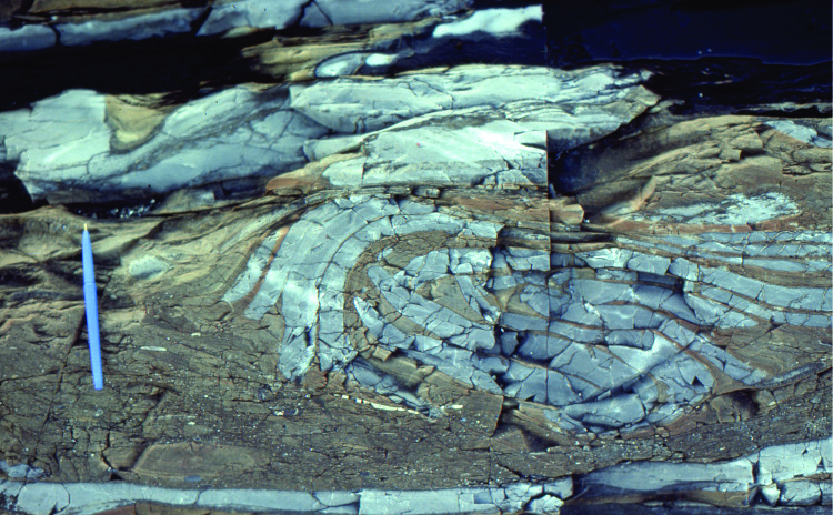
Structures formed by sediment compaction and dewatering
The term syn-sedimentary deformation tends to be used rather loosely, as deformation that takes place during or soon after deposition; the ‘soon’ is the loose part of this broad definition. Sediment begins to compact almost immediately following deposition, where framework grains move closer together. As compaction progresses, interstitial water (i.e. the water between grains at the time of deposition) is expelled, and this process in itself can deform the sediment. Water that is expelled from sediment can escape to the surface (e.g. the sea or lake floor), or it can be prevented from flowing by low permeability layers – particularly those containing mud. When this happens, local pore pressures increase, and this, in turn, reduces sediment shear strength, promoting deformation.
Note that this kind of deformation is an integral part of the Mass Transport Deposits pictured above, but it also takes place in beds where there is no wholesale slumping or sliding. Soft sediment deformation is common in conditions of rapid deposition where interstitial water is trapped, as in turbidity currents and sandy fluvial channels.
Some of the more common structures illustrated here include:
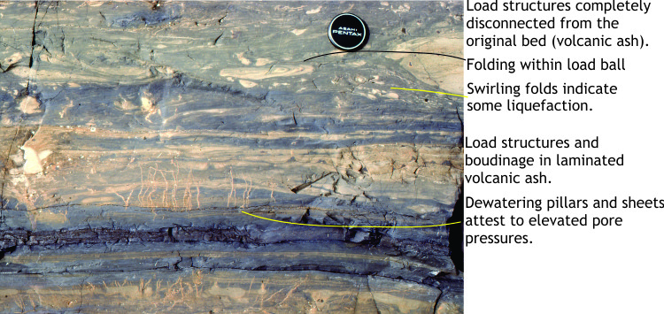
Load structures (also called load casts, or ball-and-pillow structures): Common in newly deposited beds where a higher density layer, like sand, overlies a lower density mud. Differential loading cause bulbous shaped sand bodies to project into the mud. Laminae within the load cast are also deformed. Load casts may detach completely and appear to float in the mud layer.
Flame structures: Closely spaced load casts will force relatively fluid mud upwards, forming tapered, flame-like mud wisps that protrude into the overlying sand.
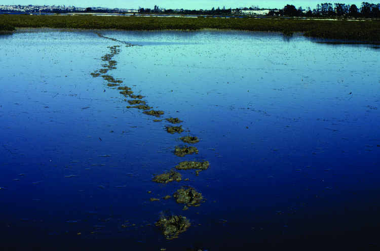
Dewatering pillars and sheets: During compaction, interstitial water may escape along preferred pathways; these escape route may be tube-like, or form as vertical sheets. Dewatering pillars and sheets that extend to the sediment surface can carry suspended muddy sediment that will accumulate around the vent as mud blisters or small mud volcanoes.
Dish structures: Dewatering of saturated sands can truncate primary laminae, forming concave-upward, or dish-shaped structures.
| Sedimentary structure | Primary attributes | Common environments |
|---|---|---|
 |
Detached load casts of volcanic ash appear to float in blue-grey mudstone. Laminae within the casts are intricately folded in the upper layer (lens cap). Load casts probably formed at about the same time as the dewatering pillars. Most of the primary bedding here was deformed soon after deposition. Paleoproterozoic, Belcher Islands. | Common in turbidites and interbedded lithologies where there are density and permeability contrasts. They indicate instability between the two layers during early compaction. |
 |
Numerous load casts at the base of the top-most sandstone (coin for scale) have protruded into the underlying dark grey mudstone. Wispy mudstone flame structures are sandwiched between the casts. Paleoproterozoic, Belcher Islands. | Flame structures are commonly associated with load casts. |
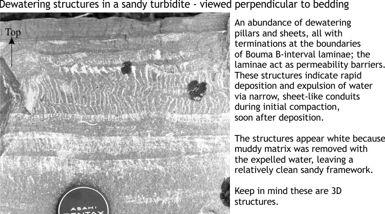 |
Bed cross-section view of dewatering pillars in the laminated (Bouma) B interval of a sandy turbidite. The pillars are white because fine matrix was removed during water expulsion. Paleoproterozoic, Belcher Islands. | Indicative of rapid deposition of water saturated sediment. Sheets are layered because of permeability contrasts in the sandstone. |
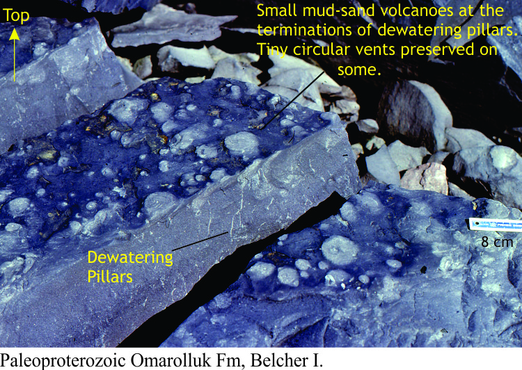 |
Bedding exposure of small blisters, or mud volcanoes at the exits of dewatering pillars. Paleoproterozoic, Belcher Islands. | |
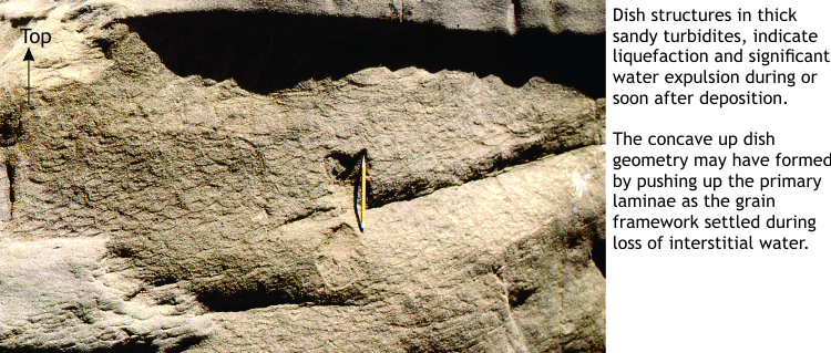 |
Dish structures in Rosario Group sandstone, San Diego. The dewatering pillars occur between adjacent dish-shaped laminae. | Indicative of rapid deposition of water saturated sediment. |
Trace fossils
Trace fossils have the privilege of being two things at once: sedimentary structures, and fossils. They occur in sediment, are made of sediment, but represent the activities of creeping, crawling or burrowing critters, mostly at or immediately below the sediment water interface (marine, lacustrine, estuarine, swamp), or subaerial environments such as dune fields. As such, trace fossils represent the range of activities that critters are normally occupied with – grazing or foraging for food, home construction and house-keeping, predating or escaping predators, wandering aimlessly, or taking a nap after an exhausting day. Some critters like to rough it, preferring the tumble of waves or strong currents, while others like the peace and quiet of deeper realms. Lives are frequently interrupted by storms or violent, turbulent flows of sand and mud; their traces, or lack of them, also reflect these events.
Most animals produce more than one kind of trace depending on what they are doing, which means that in most cases, traces reflect animal activity and biometrics, rather than the specific critter species. Most traces do not contain any remnants of the animal that made them (there are a few exceptions); finding a trilobite body fossil at the end of its scampering trail is pretty rare.
Trace fossils provide valuable information on benthic communities, environmental conditions such as wave or current energy, redox conditions (presence or absence of oxygen), rates of sedimentation, or periods of time when sedimentation slowed (e.g. hiatuses, disconformities, omission surfaces).
Intense bioturbation can also obliterate other kinds of sedimentary structures; for a geologist, this may be an annoyance or a happy circumstance. Most Precambrian successions are free of trace fossils and bioturbation; this changed during the Ediacaran, the period that appears to have been a kind of precursor to the Cambrian invertebrate explosion. Most Phanerozoic sedimentary successions (since 540 million years ago) have enjoyed the munching-burrowing efforts of a myriad nameless critters.
The images below are organized into six ethological (i.e. behavioral) structures:
-
- Resting traces: the animal is taking a break or escaping a marauding predator.
- Crawling traces: basically moving from A to B, so the emphasis is on body and limb movement.
- Grazing traces: The search for food at the sediment surface or just beneath it – one interesting analogy is the similarity to strip mining.
- Feeding structures: Like grazing, but in this group the critters burrow (subsurface mining), forming as they go, simple temporary burrows or branched burrow complexes.
- Dwelling structures: These are more permanent burrows that the animals call home.
- Escape structures: These too are temporary burrows, made while attempting an escape from sediment burial, or from predators; hence the critter may move upward or downward in the sediment, depending on the circumstances.
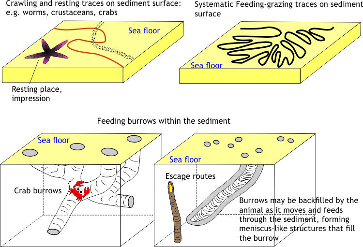
- Trace fossils can be divided into groups according to the behavior of the animals that produced them. Here are four schematics of resting, crawling grazing, feeding, dwelling, and escape activities.
| Sedimentary structure | Primary attributes | Common environments |
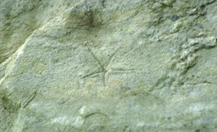 |
Resting trace: A Permian starfish, or brittle star found its final resting place on this sand bed. The impression leaves a faithful record of the size of the starfish. Ellesmere Island. | Sandy substrates, intertidal to shallow subtidal. |
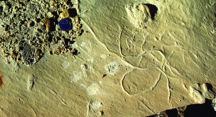 |
Crawling trace: Possibly a crustacean wending its way home, seemingly going in circles across the sea floor, or within the sediment just below it. The substrate was fine sand. | Common in many lower energy environments (away from direct wave action and strong currents) |
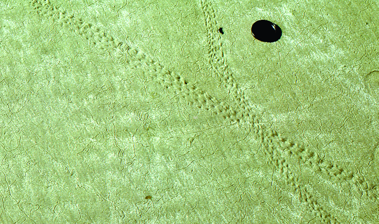 |
Crawling & Grazing traces: Recent, large crab traces with impressions from its appendages; this is a crawling trace. Look closely to see a myriad small, criss-crossing grazing trails made by small crustaceans. These examples from a sandy beach. | Intertidal to subtidal, soft substrates. |
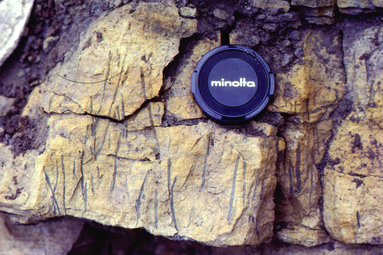
 |
Dwelling structures: The Ichnogenus Ophiomorpha – Simple burrows, vertical or obliques to bedding, typically lined with small muddy nodules, & uniform burrow fill. Commonly in sandstones that also contain evidence of shallow marine waters (e.g., fossils, crossbeds). | Shallow subtidal, sandy substrates where sediment at the sea floor is moved by waves and tidal currents. |
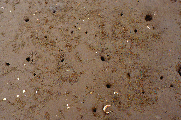 |
Dwelling structures: Modern, vertical crab burrows in firm tidal flat sand. Note the small sand nodules at the entrance to each burrow; ejected by the animal as it excavates. | Intertidal, beach, to shallow subtidal, sandy substrates where sediment at the sea floor is moved by waves and tidal currents. |
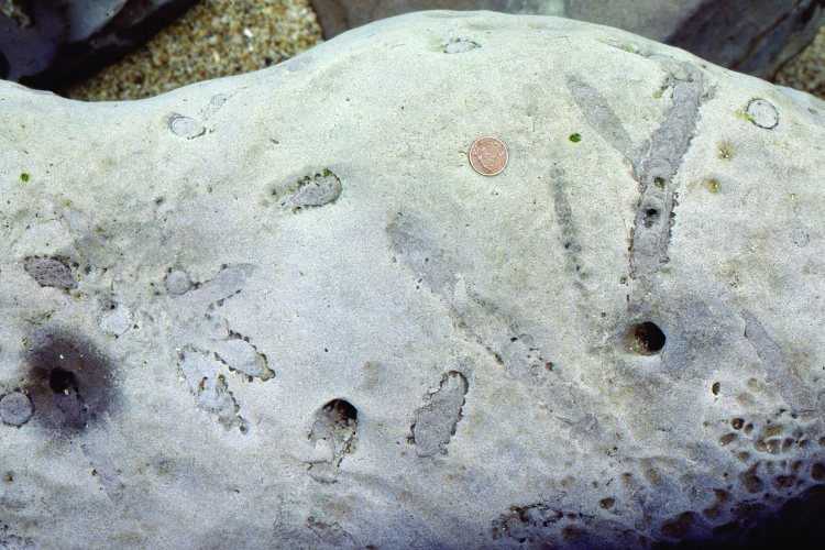
 |
Feeding traces: The ichnogenus Zoophycus has a central burrow, or stem, about which the animal grazed into the sediment in a corkscrew fashion. Two specimens in this view. | Relatively quiet conditions where surface sediment is not continuously stirred. The deep, outer shelf, slope, and basin at bathyal depths. |
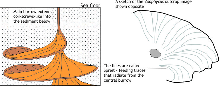 |
Schematic of basic corkscrew structures of Zoophycus. The sketch on the right outlines the central burrow and spreit (successive feeding traces) in the outcrop image above. | Feeding structures like these show systematic grazing patterns across the sediment surface and within sediment. |
 |
Escape structures: Simple vertical structures that begin from the base of a bed, reflecting the critter’s desire to escape to the sea floor | Can occur in almost any environment where rapid deposition of sediment takes place |
 |
An example of rampant and pervasive bioturbation that has all but destroyed the primary layering (parallel laminations, crossbedding) within a bed. | Can potentially occur in many environments where benthic faunas proliferate. |
Unless indicated otherwise, all the images used in this chapter are by Brian Ricketts.
Chapter Contents
- 1 Preamble
- 2 Tools at a geologist’s disposal
- 3 Some common sedimentary structures
- 3.1 Bedding
- 3.2 Crossbedding
- 3.3 Sole Structures
- 3.4 Structures formed by desiccation
- 3.5 Structures formed by sediment textures and fabrics
- 3.6 Structures formed by sediment gravity flows
- 3.7 Structures formed by mass movement (MTDs)
- 3.8 Structures formed by sediment compaction and dewatering
- 3.9 Trace fossils