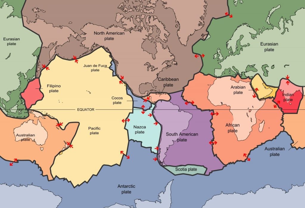
Tectonic Movement
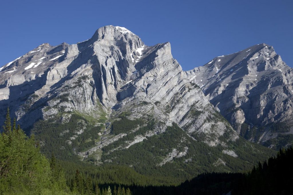
The Earth’s lithosphere is in constant motion at tectonic plate boundaries. The velocity of this movement on average is often compared with the growth rate of your fingernails. That does not sound like much but this movement has a dramatic effect on Earth’s landscape. What we view as craggy mountain peaks and valleys have all been sculpted by the movement of tectonic plates and the work of weathering and erosion. The tectonic map of the Earth found below, provides directional arrows that indicate plate movement along the major boundaries.
Most of the movement along the boundaries is imperceptible to humans in our lifespan. However, this tectonic movement over many thousands to millions of years does make major changes that account for features as dramatic as the Himalayan Mountains. Some of the movement can take place in virtually the blink of an eye. This happens when stress builds up as these solid plates attempt to re-equilibrate. The dramatic reaction to sudden release of stress results in earthquakes which can make visible changes to Earth’s surface in the form of faults, or breaks, within the solid crust. Look at the amazing before and after Google Earth images of the displacement caused by the June 2019, 7.1 magnitude earthquake in Ridgecrest, CA. This GIF was created by using satellite imagery; in these photos, you are looking down on the land surface as if you are flying overhead in a plane.
Types of Stress
The arrows that appear on the tectonic map above display three types of movement. These are the main types of stress that affect the rock of the lithosphere at plate boundaries. Compressional stress takes place where the arrows point toward each other and plates collide. This type of plate boundary is referred to as convergent because the plates are colliding. Tensional stress occurs where the arrows point away from each other and separation occurs between these plates. This type of plate boundary is referred to as divergent as the plates are moving away from each other. Shear stress results where plates attempt to slide past each other in opposite directions. This type of plate boundary is referred to as transform.
Stress is the force being exerted on the rock at each of these boundaries. Strain is the physical change that results in response to that force. The visible strain that we see in the rock is called deformation.
Let’s explain this in visual terms relative to the before/after GIF from the Ridgecrest earthquake above. The Ridgecrest earthquake is related to movement along the transform plate boundary which slices through southwestern California. Movement along this plate boundary also created the infamous San Andreas fault. This transform plate boundary has created a system of faults as it tries to slide a solid slice of southwestern California, which sits on the Pacific Plate, past the rest of California which resides on the North American Plate. This movement produces shear stress. The force of the shear stress caused a fracture to form in the crust which is a fault. The fault is the strain that occured in response to the stress produced by the shearing force. This type of physical fracturing of Earth’s crust is referred to as brittle deformation.
When rock of the Earth’s crust is subjected to increasing stress it passes through 3 successive stages of deformation:
-
-
- Elastic deformation where the strain is reversible.
- Ductile deformation (also referred to as plastic deformation); the strain is irreversible.
- Brittle deformation where the strain results in a permanent fracture of the rock.
-
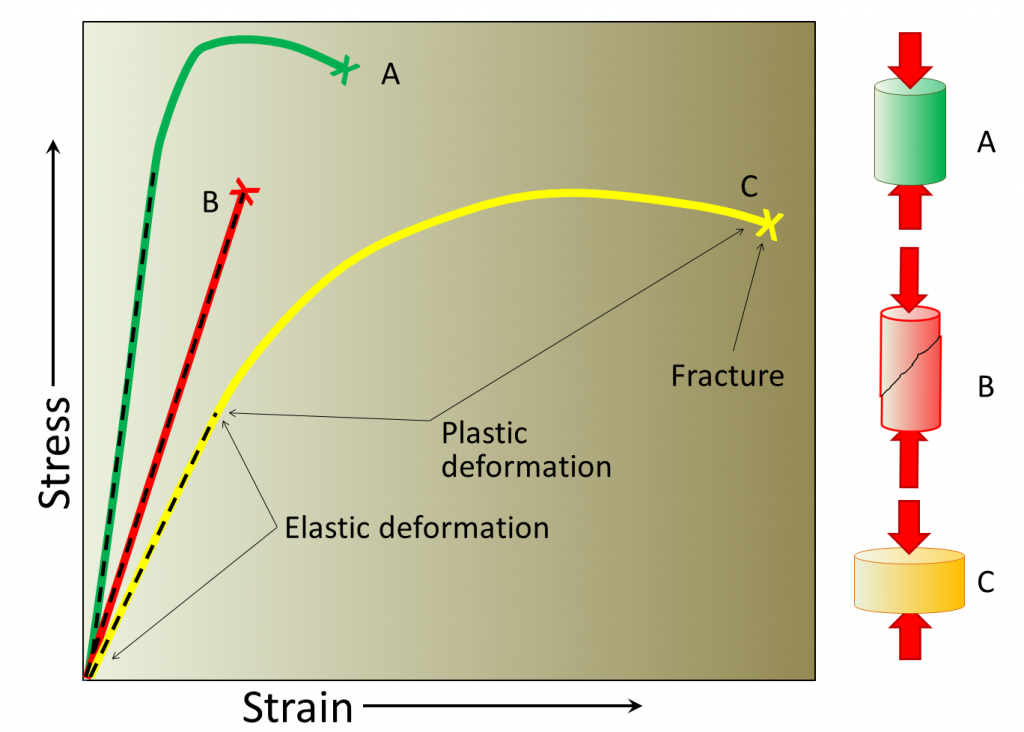
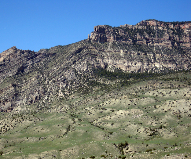
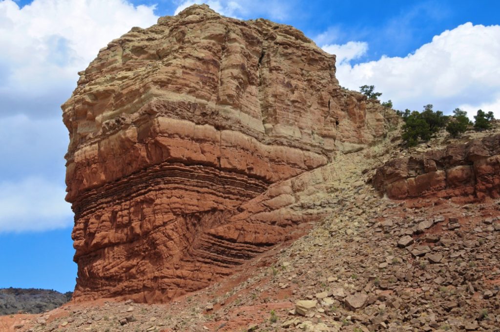
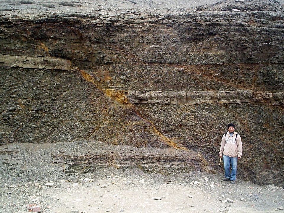
Elastic deformation of the crust would not be noticed. Ductile deformation is where things become interesting in terms of visual effects displayed in solid rock (see photo below). When sufficient stress is applied, the response will be a change in shape. This type of deformation is permanent. Brittle deformation, as described above with respect to the Ridgecrest earthquake, occurs when the physical strength of the rock is surpassed and the rock will break resulting in a permanent fracture, or fault.
Many factors contribute to how a rock will respond to applied stress including the composition and mineral structure of the rock and the temperature of the surrounding environment. Sedimentary rock often contain water in mineral structures like clay and in pore spaces between grains. This allows sedimentary rock to respond to applied stress by deforming ductilely. Most igneous rock, however, is composed of interlocking mineral crystals and contains very little water. The strong fabric of igneous rock will result in rupture to the same applied stress.
Deformation – folding
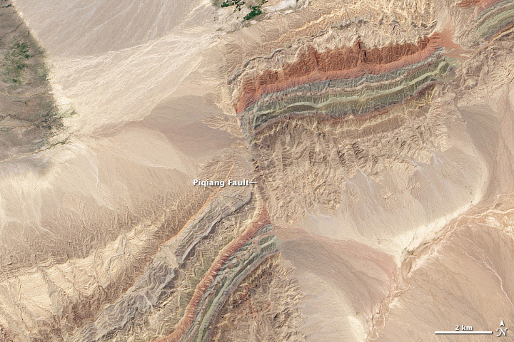
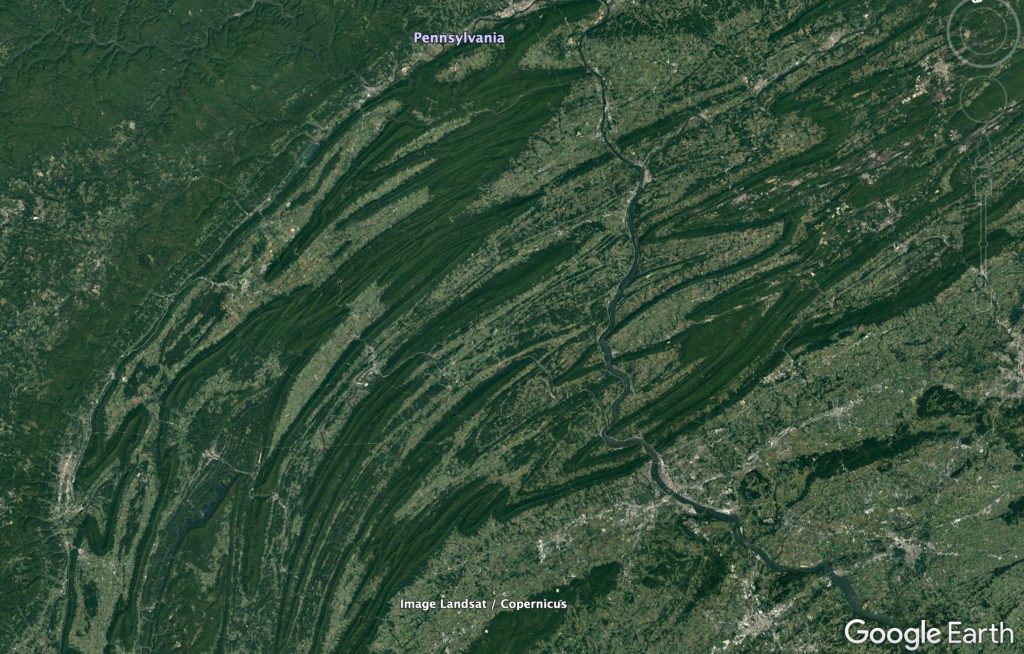
Tectonic compressional stress is the dominant force in mountain building. As plates collide, compressional stress will cause the crust to buckle and warp to produce folds. A compressional fold belt can be found in all mountain ranges around the world which have been caused by tectonic plate collision. View the Google Earth image below of the Ridge and Valley region in the Appalachian Mountains of Pennsylvania. The rock in this region includes mostly ductile sedimentary rock layers which were folded during the collision of Africa with North America as the Pangean supercontinent was being pieced together. We’re viewing this section of the Appalachians from an altitude of about 200 km. The folding pattern displayed is quite a spectacular feature seen from space.
Fold Classification
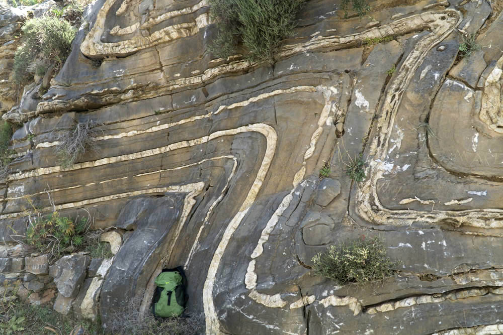
Folds are classified based on their geometry and fall into 3 general categories: monoclines, anticlines and synclines.
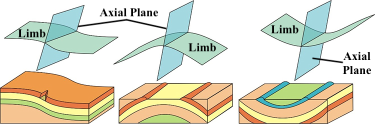
Anticlines and Synclines
Anticlines (upfolds) and synclines (downfolds) are very common geologic structures that form in pairs in response to compression. Anticlines and synclines will share a limb of the fold. Click on the starred placemarks in the gigapixel image from eastern West Virginia, below, to learn more about specific characteristics of anticlines and synclines.
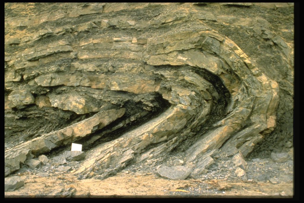
Monoclines
Monoclines (see image below) are not as common and usually form as an adjustment in the surface layers to some type of tectonic activity happening deep within the Earth’s surface. An example of this would be an uplift of a block of deeply buried “basement” rock of the continental crust.
Overturned and recumbent folds
The stress of tectonic compression is commonly applied more forcefully in one direction as one tectonic plate collides with another. The directionally applied stress may result in folding that appears to be “pushed” from one direction. When this happens, folds may begin to turn over on themselves. A fold will become increasingly asymmetric as the axial plane tips toward 90° from vertical at which time it will be classified as recumbent.
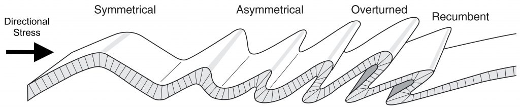
Overturned Fold
Recumbent Fold
Deformation – Faults
All rock types will ultimately reach a point of failure where they will break permanently and form a fault. Faults are classified based on the type of stress that produced them as well as the movement associated with the two separate blocks of rock. Deformational folding, as discussed above, is largely caused by compressional stress of tectonic collision. Faulting is also the result of tectonic movement however, different fault types are associated with the different types of plate boundaries. The three types of stress, compressional, tensional, and shear, are associated with movement along the three different types of plate boundaries, convergent, divergent and transform.
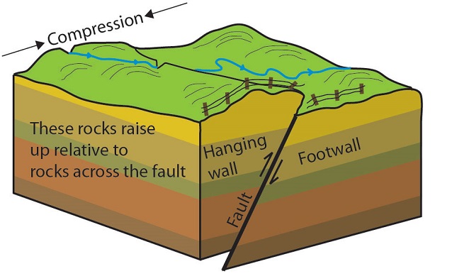
Reverse and Thrust Faults
Geologists use block diagrams in an attempt to demonstrate three dimensional movement. The terms hanging wall and footwall refer to the relative position of the blocks after movement. Economic minerals, such as gold, often form along faults planes, and these terms come from where a miner would stand, and where they would hang their lantern as they were mining the minerals along the fault plane.
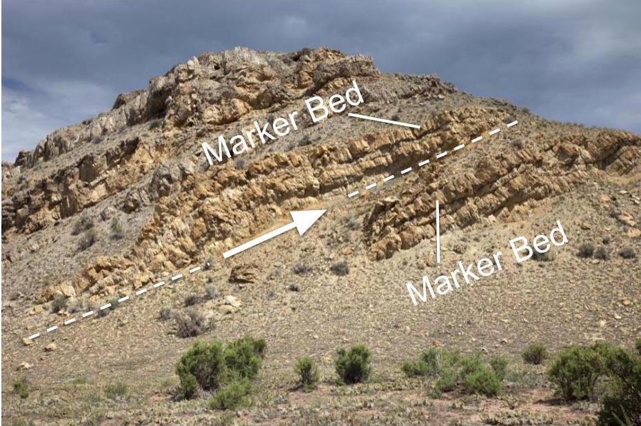
The block diagram displays horizontal sedimentary strata (layers, or beds, of sedimentary rock). When geologists look at these structures as they occur at a rock exposure, they trace marker beds to determine which block has moved and in what direction. Study the block diagram below of a reverse/thrust fault. Trace the rock layers from one side of the fault to the other.
A reverse fault is caused by compressional stress at convergent plate boundaries.
In a reverse or thrust fault, the hanging wall has moved up relative to the footwall.
The difference between a reverse and thrust fault is the angle of the fault plane. A reverse has a high angle fault plane (the surface separating the two blocks) while a thrust fault has a low angle fault plane. Take a look at the 3D models below to investigate. Once the models load, you can grab them to rotate in 3D. One common misconception by students in identifying faults is that the arrangement of the blocks is static as in the diagram above. This may lead a student to believe that the hanging wall is always on one side in a given type fault (such as on the left in the diagram above). Being able to look at these blocks in 3D allows the student to see that the hanging wall and footwall can be oriented in any direction as they occur in the Earth’s crust.
Examples of a Reverse and Thrust Fault, below, to compare with the 3D images above.
Reverse Fault
 |
Thrust Fault
 |
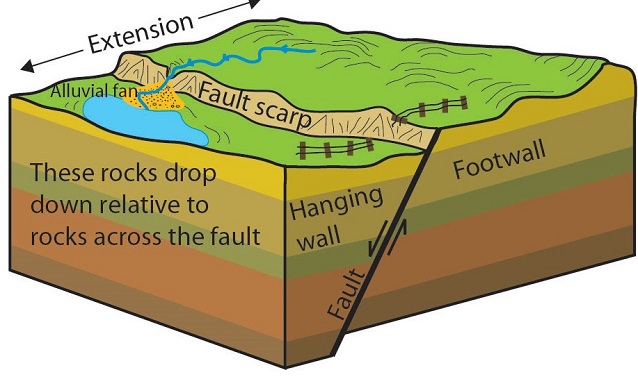
Normal Faults
A normal fault is caused by extensional (tensional) stress at divergent plate boundaries as two plates are moving in opposite directions, away from each other.
In a normal fault, the hanging wall has moved down relative to the footwall.
Explore this 3D block structure of a normal fault. Once the models load, you can grab them to rotate in 3D. One common misconception by students in identifying faults is that the arrangement of the blocks is static as in the diagram above. This may lead a student to believe that the hanging wall is always on one side in a given fault (such as on the left in the diagram above). Being able to look at these blocks in 3D allows the student to see that the hanging wall and footwall can be oriented in any direction as they occur in Earth’s crust.
 |
 |
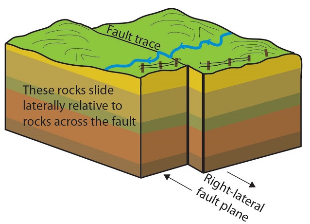
Strike-Slip Faults
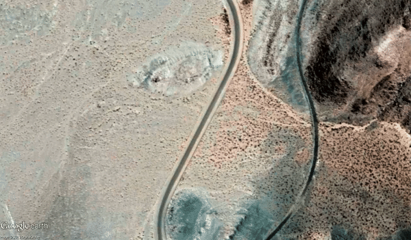
Shear stress at a transform plate boundary will produce a strike-slip fault. The fault is named strike-slip because the fracture is along the Earth’s surface and the movement between the blocks is not up or down but “along strike” – a line with a specific direction along Earth’s surface – the line of strike – which is also known as the “fault trace.” The fault plane is typically vertical into the crust and the “slip,” or movement, occurs along the plane. The strike slip fault in the diagram is labeled a “right-lateral” strike-slip fault. If you are standing on one side of the fault trace and looking across to the other side, the movement would appear to be laterally to the right. Note how the stream jogs to the right along the fault trace. In a left-lateral strike-slip fault, the blocks would be moving in the opposite direction.
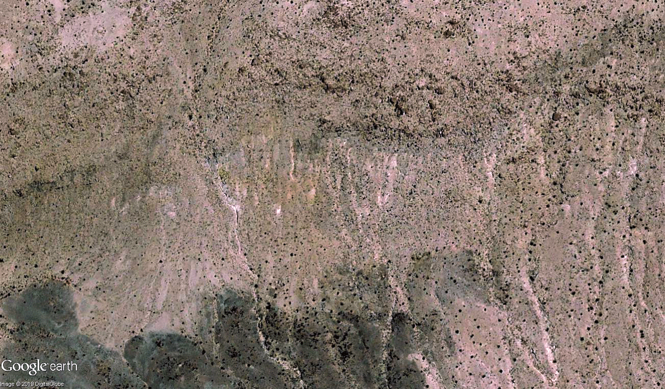
Let’s take a look at another one of these fantastic before/after Google Earth image GIFs from the Ridgecrest, CA earthquake. This GIF was created by using satellite imagery; in these photos, you are looking down on the land surface as if you are flying overhead in a plane. As you analyze the movement, put yourself on one side of the fault and look across to the the other side. Is this a right-lateral or left-lateral strike-slip fault? Find out below.
Did I get it?
The photo in the aerial photo below is of a left-lateral strike-slip fault. Note: if you were standing where the word fault is written and looking across the fault trace to the other side, the motion along fault plane would be to the left.